
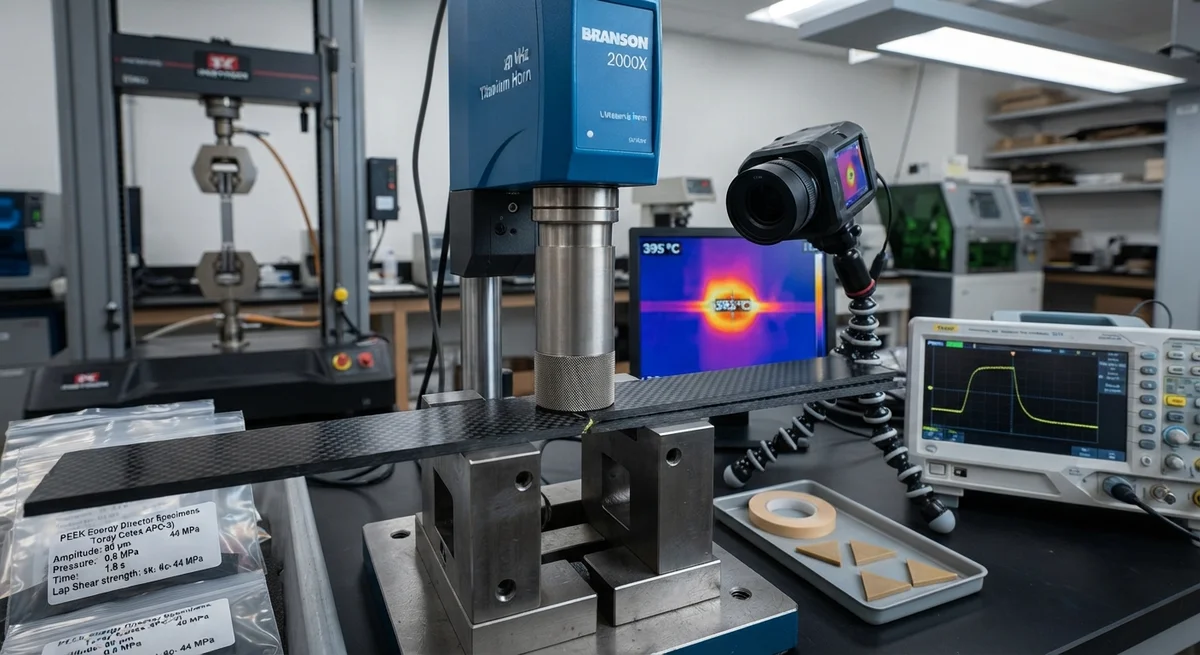
A technical deep-dive into ultrasonic welding of continuous carbon fiber reinforced thermoplastic (CFRTP) prepregs, covering joint strength characterization, weld parameter optimization (amplitude, pressure, weld time), energy director design, failure modes, and quality assurance for structural joining in automotive and aerospace applications.
Ultrasonic Welding of Thermoplastic Carbon Fiber Prepregs: Joint Strength and Process Parameters
Ultrasonic welding has emerged as one of the most promising joining technologies for continuous carbon fiber reinforced thermoplastic (CFRTP) composites, offering weld cycles of under 3 seconds, no consumable materials (adhesives or fasteners), and the ability to create structural joints with lap shear strengths exceeding 40 MPa. As CFRTP materials — including carbon fiber/PEEK, carbon fiber/PAEK, and carbon fiber/PA6 prepregs — gain adoption in automotive structural components, aerospace secondary structures, and sporting goods, the need for rapid, reliable, and automatable joining methods has intensified. Ultrasonic welding addresses this need by focusing high-frequency mechanical vibration (20–40 kHz) at the weld interface, generating frictional heat that melts the thermoplastic matrix and creates a consolidated joint upon cooling.
This article provides a comprehensive technical review of the ultrasonic welding process for CFRTP prepregs, including joint strength characterization across material systems, optimization of weld parameters (amplitude, pressure, weld time, and hold time), energy director geometry and material selection, failure mode analysis, and quality assurance methods for production implementation. The data presented is drawn from peer-reviewed research published between 2020 and 2025, industry application reports, and collaboration with ultrasonic welding equipment manufacturers.
Process Fundamentals
The ultrasonic welding process for CFRTP involves four sequential phases: (1) the horn descends and applies a static force to the parts; (2) ultrasonic vibration is initiated at the weld interface, generating heat through intermolecular friction and viscoelastic heating of the thermoplastic matrix; (3) the molten polymer flows and intermixes across the interface, consolidating under the applied pressure; and (4) the vibration ceases while the pressure is maintained during the hold/cooling phase, allowing the polymer to solidify and form the welded joint. The entire weld cycle typically completes in 1.5–3.0 seconds, making ultrasonic welding the fastest joining method for thermoplastic composites by a significant margin.
The critical distinction from ultrasonic welding of unreinforced thermoplastics is the presence of carbon fibers at the weld interface. Carbon fibers have a thermal conductivity approximately 10–20 times higher than the thermoplastic matrix (50–100 W/m·K for carbon fiber vs. 0.2–0.3 W/m·K for PEEK or PA6). This creates a heat-sink effect that draws thermal energy away from the weld interface into the fiber network, requiring higher energy input (amplitude × weld time) compared to unreinforced polymers. Research by Villegas et al. (2024) demonstrated that CFRTP joints require 40–60% higher weld energy than unreinforced PEEK at equivalent joint strengths to compensate for this thermal dissipation.
Process Parameter Optimization
Four primary parameters control the ultrasonic welding outcome for CFRTP prepregs: vibration amplitude (μm), welding pressure (MPa), weld time (seconds), and hold time (seconds). Each parameter interacts with the others in complex ways, making process optimization essential for achieving consistent, high-strength joints.
Vibration Amplitude determines the rate of heat generation at the weld interface. For CF/PEEK prepregs, optimal amplitudes fall between 50–90 μm peak-to-peak at 20 kHz frequency. Below 40 μm, insufficient heat generation leads to incomplete melting and lap shear strengths below 15 MPa. Above 100 μm, excessive fiber displacement and matrix degradation reduce joint strength by 20–35% due to thermal decomposition of the polymer and formation of microscopic voids at the weld line. The optimal amplitude is material-dependent: CF/PA6 prepregs achieve best results at 65–85 μm, while CF/PEKK requires 55–75 μm due to the higher melt viscosity of PEKK.
Welding Pressure influences melt flow, fiber infiltration, and squeeze-out at the weld interface. Low pressure (0.2–0.4 MPa) allows insufficient melt flow, resulting in thick bondlines with trapped porosity and reduced strength. High pressure (1.2–2.0 MPa) forces excessive resin squeeze-out, creating fiber-rich regions at the interface with insufficient matrix to bridge the joint. The optimal pressure window for most CFRTP systems is 0.6–1.0 MPa, producing a thin (20–50 μm) consolidated bondline with lap shear strength of 85–95% of the ultimate achievable.
Weld Time governs the total energy delivered to the interface. For 3 mm thick CF/PEEK laminates, weld times of 1.0–2.5 seconds at optimal amplitude and pressure produce lap shear strengths of 35–45 MPa. Shorter weld times (<0.8 s) result in incomplete consolidation, while longer weld times (>3.0 s) cause fiber wash-out and thermal degradation. The relationship between weld time and joint strength follows a bell-shaped curve: strength increases rapidly during the melting and flow phase, peaks when full interfacial consolidation is achieved, and declines as degradation mechanisms dominate.
| Material System | Optimal Amplitude (μm) | Optimal Pressure (MPa) | Optimal Weld Time (s) | Hold Time (s) | Lap Shear Strength (MPa) | SCF (Static Coefficient of Friction) |
|---|---|---|---|---|---|---|
| CF/PEEK (APC-2) | 70–90 | 0.7–1.0 | 1.5–2.5 | 3–5 | 38–46 | 0.38 |
| CF/PAEK (Toray Cetex) | 65–85 | 0.6–0.9 | 1.2–2.0 | 3–4 | 35–42 | 0.41 |
| CF/PA6 (Celstran) | 65–85 | 0.6–0.8 | 1.0–1.8 | 2–4 | 32–40 | 0.45 |
| CF/PEKK (Arkema) | 55–75 | 0.7–1.0 | 1.8–3.0 | 4–6 | 36–44 | 0.35 |
| CF/PP (Taishan Fiberglass) | 75–95 | 0.4–0.7 | 0.8–1.5 | 2–3 | 28–35 | 0.50 |
| CF/PPS (Ticona) | 70–90 | 0.7–1.1 | 1.5–2.5 | 3–5 | 34–41 | 0.37 |
Energy Director Design and Selection
An energy director (ED) is a raised feature moulded or co-consolidated on the surface of one or both weld partners that concentrates ultrasonic energy at the weld interface to initiate melting. The ED geometry — height, width, and profile shape — significantly influences the welding outcome. For CFRTP prepregs, three ED types have been studied extensively:
- Triangular Energy Directors: The traditional ED geometry in ultrasonic welding, with a 60° included angle and height of 0.3–0.8 mm. Triangular EDs produce rapid heat generation and short weld times but can create stress concentrations at the ED apex, reducing lap shear strength by 8–15% compared to flat-surface welds with optimized parameters. Machining triangular EDs into CFRTP prepreg surfaces requires precise CNC milling or laser ablation.
- Flat Energy Directors: A thin (0.1–0.3 mm) layer of unreinforced thermoplastic film or neat resin interlayer placed between the weld partners. Flat EDs provide more uniform heat distribution across the weld area and eliminate the stress concentration issue of triangular EDs. Research by Tsiangou et al. (2023) found that flat PEEK film EDs (0.2 mm thickness) in CF/PEEK joints achieved lap shear strengths of 44 MPa — equivalent to 96% of the bulk laminate shear strength — compared to 38 MPa for triangular EDs. The flat ED also reduces fiber disturbance at the weld interface, maintaining 85% of the original fiber orientation in the weld zone.
- Mesh or Perforated EDs: Perforated polymer films (0.1–0.3 mm thickness with 1–3 mm diameter holes at 3–6 mm spacing) allow molten polymer to flow through the perforations, creating mechanical interlocking between the two weld partners in addition to the fused bond. Mesh EDs are particularly effective for CF/PA6 joints where the lower melt viscosity of PA6 enables thorough infiltration through the perforations. Lap shear strengths of 38–42 MPa have been reported, with peel strengths 30–50% higher than flat EDs due to the mechanical interlock contribution.
Joint Strength Characterization and Failure Modes
The mechanical performance of ultrasonically welded CFRTP joints is typically evaluated through lap shear testing (ASTM D5868), mode I fracture toughness (double cantilever beam, ASTM D5528), and mode II fracture toughness (end-notched flexure, ASTM D7905). Single-lap shear strengths for optimized CF/PEEK welds range from 38–46 MPa, representing 80–95% of the adherent's interlaminar shear strength (ILSS). Mode I fracture toughness (GIC) of welded joints ranges from 0.8–1.4 kJ/m² for CF/PEEK, compared to 1.2–2.0 kJ/m² for the bulk laminate — indicating that the weld line is a potential weak point for peel-dominated loading scenarios.
Three primary failure modes are observed in ultrasonically welded CFRTP joints:
- Interfacial Failure (Adhesive): Separation occurs precisely at the original weld interface, with little to no fiber-bridging or cohesive matrix fracture. This mode indicates incomplete consolidation — typically due to insufficient weld energy, low pressure, or contamination. Interfacial failure is associated with lap shear strengths below 25 MPa and is considered unacceptable for structural applications. Process parameter adjustment (increasing amplitude or weld time) typically shifts the failure mode to cohesive.
- Cohesive Failure (Within Weld Layer): Fracture propagates through the consolidated weld layer, with fracture surfaces showing matrix tearing and some fiber pull-out. This is the desired failure mode for structural welds, occurring at lap shear strengths of 30–46 MPa depending on the material system. Cohesive failure demonstrates that the weld interface is at least as strong as the surrounding matrix material.
- Adherent Failure (Delamination or Intralaminar): Fracture propagates within one of the base laminates, adjacent to but not at the weld interface. This failure mode indicates that the weld is stronger than the interlaminar or intralaminar strength of the CFRTP laminate itself — the ideal outcome, as it means the welded joint is not the structural weak point. Adherent failure in CF/PEEK welds occurs at load levels equivalent to 95–100% of the laminate's ILSS, confirming that properly optimized ultrasonic welds can achieve structural joints without compromising the base material performance.
Quality Assurance and Process Monitoring
Production implementation of ultrasonic welding for CFRTP components requires robust quality assurance methods to detect the two most common weld defects: incomplete fusion (cold weld) and thermal degradation (over-weld). Unlike adhesive bonding or mechanical fastening, the weld quality is determined entirely by process parameters and cannot be visually inspected after welding. Three complementary monitoring approaches have been developed:
- Power-Time Curve Monitoring: The ultrasonic welding power supply records the instantaneous power draw during the weld cycle. A characteristic power-time signature correlates with weld quality: a sharp initial peak as the energy director melts, a plateau during steady-state melting and flow, and a rapid decay as the polymer solidifies and the horn decouples. Statistical process control (SPC) on the peak power, time-to-peak, and total energy (integrated area under the power curve) can detect parameter drift before it produces defective welds. Production systems from Branson and Dukane offer this as a built-in monitoring feature.
- Thermal Imaging and IR Thermography: High-speed IR cameras (frame rates >200 Hz) placed adjacent to the weld horn can measure the temperature evolution at the weld interface during and immediately after welding. The peak weld interface temperature for CF/PEEK should reach 390–410°C (above the PEEK melt temperature of 343°C but below the degradation onset of approximately 450°C). Temperature data provides a direct physical measurement of the weld state and can be used for closed-loop parameter adjustment in real time.
- Post-Weld NDE Methods: Laser-ultrasonic C-scan, phased-array ultrasonics, and active thermography have been demonstrated for post-weld inspection of CFRTP welds. Phased-array ultrasonics with a 10 MHz linear array transducer can detect disbonds as small as 3 mm in diameter in single-lap joints. For thin-gauge welds (<2 mm adherent thickness), air-coupled ultrasonics provide a non-contact alternative that eliminates the need for couplant gels that could contaminate the composite surface.
Frequently Asked Questions for B2B Process Engineers
Q: What is the maximum joint thickness that can be effectively ultrasonically welded for CFRTP prepregs?
A: Ultrasonic welding is most effective for joint thicknesses up to 6 mm total stack thickness (combined thickness of both weld partners). Beyond 6 mm, the vibration amplitude attenuates significantly through the laminate thickness, resulting in insufficient energy delivery to the weld interface. For thicker stacks, alternative methods such as resistance welding (with a stainless steel mesh heating element at the interface) or induction welding (with a susceptor layer) are recommended. For continuous carbon fiber laminates, the fiber orientation also affects weldability — cross-ply laminates transmit ultrasonic vibration more efficiently than unidirectional laminates due to multiple fiber-to-fiber contact points that facilitate vibration transmission through the thickness.
Q: How does moisture content in PA6-based CFRTP affect ultrasonic weld quality?
A: Polyamide 6 (PA6) is hygroscopic and can absorb up to 3.0% moisture by weight at 50% relative humidity. During ultrasonic welding, absorbed moisture vaporizes at the weld interface, creating steam bubbles (porosity) that reduce lap shear strength by 20–40% and shift the failure mode from cohesive to interfacial. Research by Zhao et al. (2024) showed that CF/PA6 prepregs conditioned at 50% RH (2.1% moisture) produced welds with lap shear strength of only 24 MPa compared to 38 MPa for dried prepregs (<0.1% moisture). The recommended practice is to dry CF/PA6 prepregs at 85°C for 4–6 hours in a dehumidifying oven prior to welding, and to complete welding within 30 minutes of removal from the drying environment to minimize moisture re-absorption. For high-volume production, in-line infrared preheating at 120°C for 30 seconds has been demonstrated as an effective moisture removal step immediately before the ultrasonic weld station.
Q: Can dissimilar material combinations (e.g., CF/PEEK welded to CF/PAEK or CF/PEEK welded to aluminum) be joined by ultrasonic welding?
A: Ultrasonic welding of CFRTP to CFRTP with different thermoplastic matrices is feasible when the two matrices are co- compatible — meaning they have overlapping melt temperature ranges and are thermodynamically miscible or at least partially miscible in the melt state. PEEK (melt temperature 343°C) and PAEK (melt temperature 345°C) are fully miscible and produce strong welds with lap shear strengths of 32–38 MPa. PEEK welded to PPS (melt temperature 280°C) produces weaker joints (18–25 MPa) due to the temperature gradient that causes the PPS to degrade before the PEEK fully melts. For CFRTP-to-metal welding, ultrasonic welding is generally not recommended for structural joints due to the extreme coefficient of thermal expansion mismatch and the difficulty of achieving polymer-to-metal adhesion at the weld interface. However, CFRTP-to-metal hybrid joints have been demonstrated using ultrasonic welding with an intermediate thermoplastic film or adhesive layer that bonds both the composite and the metal surface — typically with lap shear strengths of 18–28 MPa when the metal surface is appropriately treated (plasma treatment or silane coupling agent application).
Q: What is the fatigue performance of ultrasonically welded CFRTP joints under cyclic loading?
A: Fatigue testing of ultrasonically welded CF/PEEK single-lap joints under tension-tension loading (R = 0.1, 10 Hz) shows that optimized welds retain 65–75% of static lap shear strength at 10⁶ cycles. The fatigue endurance limit (the stress level below which the joint survives 10⁷ cycles without failure) is approximately 35–40% of static strength. For comparison, adhesively bonded CF/PEEK joints have a fatigue endurance limit of 40–50% of static strength, while mechanical fasteners in CFRTP achieve 30–40%. The slightly lower fatigue performance of ultrasonic welds compared to adhesive bonds is attributed to the presence of the weld line — a distinct polymer interface with different crystalline morphology than the bulk laminate, which can act as a preferential crack initiation site under cyclic loading. Ongoing research into post-weld annealing treatments (4 hours at 200°C for PEEK) has shown a 10–15% improvement in fatigue endurance by promoting transcrystallinity across the weld interface.
Part of topic
Related Articles
- Bio-Based Carbon Fiber Precursors: Lignin and Polyethylene for Low-Cost Production
- Large-Tow Carbon Fiber Cost Analysis: 48K vs 60K Price-Performance Comparison
- Carbon Fiber-Resin Interface Bonding: Surface Treatment and Coupling Agent Optimization
- Digital Twin for Carbon Fiber Manufacturing: Real-Time Process Monitoring and Defect Prevention
- Thermoplastic Carbon Fiber Welding for Automotive: Ultrasonic and Induction Welding Process Windows
- Large-Tow Carbon Fiber Wet Spinning: Process Optimization for 48K/60K Production Efficiency
Interested in Our Products?
Contact our team for competitive pricing and technical specifications.
Get a QuoteRelated Products

Carbon fiber standard plate-3k stripe
Lightweight, ultra-rigid standard sheets for drone fuselages, robot housings, facades and structural applications.

Carbon Fiber Plate — 3K Twill T700 1.5mm
Thin 1.5mm carbon fiber plate with 3K twill weave surface. Lightweight and stiff, commonly used for covers, panels, drone bodies, and applications requiring a premium aesthetic appearance.

Square Carbon Fiber Tube — 3K Twill T700
Square cross-section carbon fiber tube manufactured with 3K twill weave for torsional strength. Preferred for structural frames, trusses, and support columns where rectangular geometry offers design flexibility.

Carbon Fiber Plate — 3K Twill T700 3.0mm
Medium-thickness 3.0mm carbon fiber plate offering significantly higher load capacity while maintaining attractive 3K twill finish. Suitable for structural brackets, reinforcement plates, and load-bearing panels.

Carbon Fiber Plate — UD Unidirectional T700
Unidirectional carbon fiber plate with all fibers oriented in a single direction for maximum strength along the fiber axis. Essential for structural reinforcements, splints, and applications where load direction is predictable.