
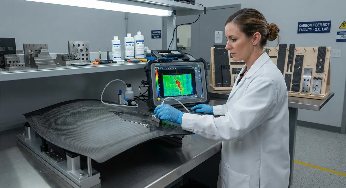
Comprehensive guide to phased array ultrasonic testing (PAUT) for carbon fiber composite inspection. Covers thickness measurement techniques, delamination detection standards per ASTM E2700 and EN 12680-3, probe selection criteria, calibration procedures, and defect acceptance thresholds for aerospace and automotive applications.
Introduction
Phased Array Ultrasonic Testing (PAUT) has become the gold standard for non-destructive evaluation of carbon fiber reinforced polymer (CFRP) components in aerospace, automotive, wind energy, and high-performance sporting goods. Unlike conventional single-element ultrasonic testing, PAUT uses an array of piezoelectric elements that can be electronically phased to steer, focus, and scan the ultrasonic beam without mechanical movement. This enables faster inspection speeds, higher resolution, and the ability to inspect complex geometries that are common in composite structures.
This article provides a technical overview of PAUT principles applied to carbon fiber composites, with emphasis on thickness measurement accuracy, delamination detection protocols, and the relevant international standards governing acceptance criteria.
Fundamentals of Phased Array Testing for Composites
PAUT probes for CFRP inspection typically use linear arrays with 32 to 128 elements operating at frequencies between 2.25 MHz and 15 MHz. The choice of frequency represents a trade-off between penetration depth and resolution:
| Frequency (MHz) | Typical CFRP Thickness Range (mm) | Resolution (mm) | Application |
|---|---|---|---|
| 2.25 | 25-100 | 1.5-3.0 | Thick laminates, wind turbine blades |
| 5.0 | 10-50 | 0.8-1.5 | Aerospace primary structure, automotive |
| 7.5 | 5-25 | 0.5-0.8 | Thin aerospace panels, prepreg layups |
| 10.0 | 2-15 | 0.3-0.5 | Thin skins, honeycomb facesheets |
| 15.0 | 1-8 | 0.2-0.4 | Thin laminates, high-resolution inspection |
For most aerospace-grade CFRP components with thicknesses between 4-30 mm, a 5 MHz or 7.5 MHz linear array with 0.5-1.0 mm element pitch provides the optimal balance of penetration and flaw detection sensitivity.
Thickness Measurement: Method and Accuracy
Thickness measurement in CFRP using PAUT relies on time-of-flight (TOF) measurement of the backwall echo. The thickness t is calculated as: t = (v x dt) / 2 where v is the longitudinal wave velocity in the composite (typically 2800-3100 m/s for CFRP, depending on fiber volume fraction and layup) and dt is the round-trip transit time.
Key factors affecting measurement accuracy include:
- Velocity variation: Fiber volume fraction variation of +/-3% can cause velocity changes of +/-50 m/s, translating to +/-1.7% thickness error if uncorrected
- Temperature effects: Velocity decreases approximately 0.5-1.0 m/s per degree C as temperature rises
- Couplant consistency: Water path or gel couplant thickness must be compensated in the TOF calculation
- Surface roughness: Surface profile deviations greater than 0.1 mm RMS introduce random TOF scatter
With proper calibration on a reference standard of known thickness, PAUT can achieve thickness measurement accuracy of +/-0.05 mm for laminates up to 25 mm thick, meeting the requirements of ASTM E2700 and EN 12680-3.
Delamination Detection Standards
Delamination is the most critical defect type in CFRP components as it directly reduces interlaminar shear strength and can propagate under cyclic loading. PAUT detection of delaminations follows these standardized acceptance criteria:
| Standard | Application | Maximum Allowable Delamination Size | Inspection Frequency |
|---|---|---|---|
| ASTM E2700 | General composites | 6 mm (any dimension) | 5 MHz min. |
| EN 12680-3 | Aerospace composites | 3 mm for primary structure | 7.5 MHz min. |
| NAS 410 | NADCAP certified | 3 mm for Class A; 6 mm Class B | Per written procedure |
| ISO 24078 | Wind energy composites | 10 mm for blade shells | 2.25-5 MHz |
A delamination is identified in the PAUT A-scan as an intermediate echo between the front-wall and back-wall signals, with amplitude exceeding a defined gate threshold (typically -6 dB relative to the back-wall echo amplitude). In C-scan imaging, delaminations appear as regions of reduced back-wall echo amplitude coupled with intermediate reflections.
Calibration Procedures
Accurate PAUT inspection of CFRP requires rigorous calibration using reference standards that match the acoustic properties of the material under test. The calibration process includes:
- Velocity calibration: Using a step wedge of known thickness increments (typically 5, 10, 15, 20 mm) made from the same CFRP material as the test article
- Sensitivity calibration: Using reference reflectors - flat-bottom holes (FBH) of 1.5 mm, 3 mm, and 6 mm diameter at 50% thickness depth in a reference block
- Time-corrected gain (TCG): Building a TCG curve to compensate for attenuation losses through the thickness of the composite
- Dead zone characterization: Identification of the near-surface dead zone (typically 1-3 mm for 5 MHz probes) where front-wall ringing masks near-surface defects
Advanced Techniques: Full Matrix Capture and Total Focusing Method
Recent advances in PAUT instrumentation have introduced Full Matrix Capture (FMC) with Total Focusing Method (TFM) reconstruction for CFRP inspection. FMC/TFM captures time-domain signals from every transmitter-receiver pair combination in the array, then uses software-based beamforming to create a high-resolution image of the entire inspection volume. This technique offers several advantages for composite inspection:
- Improved sensitivity to small delaminations (down to 1 mm diameter)
- Better signal-to-noise ratio in high-attenuation materials
- Ability to image complex geometries with curvature compensation
- Reduced inspection time through full-volume capture in a single pass
Field trials on aerospace CFRP panels have demonstrated that FMC/TFM detects 95% of implanted delaminations down to 2 mm, compared to 82% for conventional PAUT with sectorial scanning.
Common Artifacts and Pitfalls
Several factors can produce false indications or mask real defects during PAUT of CFRP:
- Porosity clusters: High porosity (greater than 3%) produces broad-spectrum attenuation that can mask deeper delaminations
- Wrinkle indications: Fiber waviness generates angle-dependent echo variations that may be misinterpreted as delaminations
- Couplant variations: Inconsistent water flow or gel application creates amplitude fluctuations in C-scan images
- Edge effects: Geometric echoes from part edges or holes can trigger false gate alarms
Operators must be trained to differentiate these artifacts through pattern recognition and multi-angle interrogation protocols.
Conclusion
Phased array ultrasonic testing provides the speed, resolution, and reliability required for quality assurance of carbon fiber composite components in demanding applications. When properly calibrated to recognized standards (ASTM E2700, EN 12680-3, NAS 410) and operated by certified technicians, PAUT achieves thickness measurement accuracy within +/-0.05 mm and reliably detects delaminations below 3 mm in critical aerospace structures. The growing adoption of FMC/TFM technology promises further gains in detection sensitivity and inspection throughput, making PAUT an increasingly indispensable tool for CFRP manufacturing quality control.
FAQ
What is the minimum delamination size detectable with PAUT in CFRP?
Under optimal conditions with a 5-10 MHz probe, PAUT can detect delaminations as small as 2-3 mm in diameter. However, industry standards typically set the critical reporting threshold at 3 mm for primary aerospace structure (EN 12680-3) and 6 mm for general applications (ASTM E2700).
Why can't conventional single-element UT inspect complex CFRP geometries effectively?
Single-element UT requires mechanical scanning and has limited beam steering capability. PAUT's electronic beam steering enables inspection of curved surfaces, tapered sections, and complex contours without mechanical repositioning. PAUT also offers multiple focal laws in a single pass, reducing inspection time by 60-80% compared to conventional UT.
How does fiber volume fraction affect PAUT thickness measurement accuracy?
Fiber volume fraction (Vf) directly affects longitudinal wave velocity in CFRP. A change of +/-3% in Vf produces approximately +/-50 m/s change in velocity, which translates to a +/-1.7% error in thickness measurement if the velocity is not recalibrated for the specific material batch.
What is the near-surface dead zone in PAUT and how is it mitigated?
The near-surface dead zone is a region 1-3 mm below the front surface where the initial pulse ringing masks echoes from shallow defects. It is mitigated by using delay-line wedges, dual-element probes, or FMC/TFM techniques that separate the transmission and reception events in time.
Is PAUT suitable for thick carbon fiber wind turbine blades?
Yes. For wind turbine blade sections up to 100 mm thick, low-frequency (2.25 MHz) PAUT probes provide adequate penetration. ISO 24078 outlines specific procedures for thick composite inspection. However, thick laminates with high fiber content may require dual-side access or lower-frequency probes to achieve full through-thickness coverage.
Part of topic
Related Articles
- Bio-Based Carbon Fiber Precursors: Lignin and Polyethylene for Low-Cost Production
- Large-Tow Carbon Fiber Cost Analysis: 48K vs 60K Price-Performance Comparison
- Carbon Fiber-Resin Interface Bonding: Surface Treatment and Coupling Agent Optimization
- Digital Twin for Carbon Fiber Manufacturing: Real-Time Process Monitoring and Defect Prevention
- Thermoplastic Carbon Fiber Welding for Automotive: Ultrasonic and Induction Welding Process Windows
- Large-Tow Carbon Fiber Wet Spinning: Process Optimization for 48K/60K Production Efficiency
Interested in Our Products?
Contact our team for competitive pricing and technical specifications.
Get a QuoteRelated Products

Carbon fiber standard plate-3k stripe
Lightweight, ultra-rigid standard sheets for drone fuselages, robot housings, facades and structural applications.

Carbon Fiber Plate — 3K Twill T700 3.0mm
Medium-thickness 3.0mm carbon fiber plate offering significantly higher load capacity while maintaining attractive 3K twill finish. Suitable for structural brackets, reinforcement plates, and load-bearing panels.

Carbon Fiber Plate — 3K Twill T700 1.5mm
Thin 1.5mm carbon fiber plate with 3K twill weave surface. Lightweight and stiff, commonly used for covers, panels, drone bodies, and applications requiring a premium aesthetic appearance.

Custom Carbon Fiber Medical Device Components
Medical-grade carbon fiber components manufactured for imaging equipment, surgical instruments, and patient support systems. Carbon fiber's radiolucency (X-ray transparency) and high strength-to-weight ratio make it ideal for CT scanner beds, wheelchair frames, surgical robot arms, and MRI-compatible accessories. Biocompatible resin systems available.

Square Carbon Fiber Tube — 3K Twill T700
Square cross-section carbon fiber tube manufactured with 3K twill weave for torsional strength. Preferred for structural frames, trusses, and support columns where rectangular geometry offers design flexibility.