
Carbon Fiber Trimming and Cutting: Waterjet vs Laser vs CNC Routing for Clean Edges Summary Edge quality is one of the most critical yet often underestimated factors in carbon fiber part production. This article presents a comparative technical...
Carbon Fiber Trimming and Cutting: Waterjet vs Laser vs CNC Routing for Clean Edges
Summary
Edge quality is one of the most critical yet often underestimated factors in carbon fiber part production. This article presents a comparative technical analysis of the three primary CFRP trimming methods — abrasive waterjet cutting, laser cutting, and CNC routing — examining cut quality, productivity, operating costs, and process limitations based on production data from multiple composite manufacturing facilities.
Introduction
After a carbon fiber laminate is cured, the part must be trimmed to its final net shape. This seemingly straightforward step accounts for 15–25% of total part manufacturing cost (Boeing, 2023) and is the leading source of part rejection due to delamination, fibre pull-out, and thermal damage. Selecting the appropriate trimming technology directly impacts yield, cycle time, and downstream assembly quality.
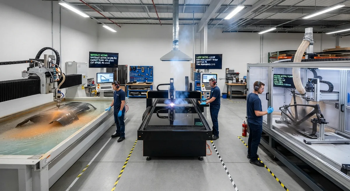
Three technologies dominate industrial CFRP trimming: abrasive waterjet cutting, laser cutting, and CNC routing with diamond tooling. Each presents distinct trade-offs in edge quality, speed, capital investment, and operating expense.
Abrasive Waterjet Cutting
Abrasive waterjet (AWJ) cutting uses a high-pressure stream of water (typically 3,800–6,200 bar / 55,000–90,000 psi) mixed with garnet abrasive particles to erode the CFRP material. It is the most widely used method for bulk trimming of cured carbon fiber parts.
Process Mechanics
The AWJ cutting head passes over the part at a standoff distance of 1.5–3.0 mm. The waterjet stream, typically 0.76–1.02 mm in orifice diameter, carries 80–120 mesh garnet at a flow rate of 300–600 g/min. Material removal occurs through micro-erosion rather than thermal ablation, making AWJ inherently free of heat-affected zones (HAZ).
Edge Quality Characteristics
Table 1: Abrasive Waterjet Cutting Performance on 3 mm CFRP Laminate| Parameter | Optimal Settings | Sub-optimal Settings |
| Kerf width (entry) | 0.9–1.1 mm | 1.2–1.5 mm |
| Kerf taper angle | 0.5–1.2° | 2.5–5.0° |
| Surface roughness (Ra) | 3–6 µm | 8–15 µm |
| Delamination at entry | None | Minor (factor < 1.05) |
| Delamination at exit | None to minor | Moderate (factor 1.1–1.3) |
| Moisture absorption after cutting | +0.8–1.5% (by weight) | +2.0–3.5% |
| Cutting speed (3 mm laminate) | 800–1,200 mm/min | 400–600 mm/min |
Advantages
- No thermal damage: CFRP is unaffected by cutting temperature — ideal for edges that will carry structural loads
- No dust generation: water suppresses airborne carbon fibre particles (OSHA PEL compliance simplified)
- Multi-layer cutting: stacks of 3–5 laminates can be cut simultaneously, improving throughput
- Thick-section capability: reliable cuts up to 25 mm, beyond practical limits for laser cutting
- No tool wear: garnet is consumed as the cutting medium, eliminating tool replacement downtime
Disadvantages
Laser Cutting
Laser cutting of CFRP has advanced significantly with the adoption of multi-kilowatt fibre lasers and ultrafast (picosecond/femtosecond) pulse lasers. The technology offers the highest throughput for thin laminates but carries inherent risks of thermal degradation.
Technology Comparison
Table 2: Laser Types for CFRP Cutting — Comparative Performance| Parameter | CO₂ Laser (10.6 µm) | Fibre Laser (1.07 µm) | Ultrafast Picosecond |
| Typical power | 3–8 kW | 2–6 kW | 50–200 W (peak > 10 MW) |
| Max. cutting depth (CFRP) | 3–5 mm | 2–4 mm | 1–3 mm |
| HAZ width | 200–600 µm | 150–400 µm | < 50 µm |
| Cutting speed (2 mm) | 3,000–5,000 mm/min | 2,500–4,000 mm/min | 100–300 mm/min |
| Operating cost per part | Medium | Low | Very high |
| Capital equipment cost | €200K–400K | €250K–500K | €500K–1.2M |
| Fibre/resin burning | Moderate | Low | Negligible |
Thermal Damage Mitigation
The primary concern with laser cutting CFRP is the heat-affected zone, where the epoxy matrix is thermally degraded. The degradation temperature of standard epoxy systems (e.g., epoxy Tg of 180°C) is exceeded within 200–600 µm of the cut edge. Mitigation strategies include:
CNC Routing with Diamond Tooling
CNC routing remains the benchmark for absolute edge quality in CFRP finishing operations. It is the preferred method for final trimming of components that will be visible in the finished product (Class A surfaces).
Tooling and Process Parameters
- Tool material: polycrystalline diamond (PCD) or CVD diamond-coated tungsten carbide
- Cutting speed: 4,000–12,000 surface metres per minute
- Feed rate: 1,500–4,000 mm/min (dependent on laminate thickness and fibre orientation)
- Chip load: 0.05–0.15 mm/tooth
- Step-over: 30–50% of tool diameter for roughing, 10–20% for finishing
- Coolant: compressed air or mist coolant (never flood coolant — moisture absorption risk)
Edge Quality
CNC routing produces the best edge quality of the three methods, with typical Ra values of 0.8–2.5 µm and zero delamination when parameters are optimised. The mechanical nature of the cut produces a clean, well-defined edge with no taper and no HAZ.
Limitations
Comparative Cost Analysis
Table 3: Cost Comparison of CFRP Trimming Methods (3 mm laminate, 1,000 parts/year)| Cost Category | Waterjet | Laser (Fibre 4 kW) | CNC Routing |
| Equipment cost | €180,000–350,000 | €250,000–500,000 | €120,000–250,000 |
| Consumables per part | €3.20–5.80 (garnet + water) | €1.10–2.50 (gas + electricity) | €4.50–9.00 (tooling) |
| Energy per part | €0.30–0.60 | €0.80–1.50 | €0.40–0.80 |
| Labour per part | €1.50–3.00 | €0.75–1.50 | €2.00–4.00 |
| Part reject rate | 2–5% | 4–8% | 1–3% |
| Scrap/rework cost per part | €4.00–10.00 | €8.00–16.00 | €2.00–6.00 |
| Total unit cost | €9.00–19.40 | €10.65–21.50 | €8.90–19.80 |
Selection Guidelines
The optimal trimming method depends on part geometry, laminate thickness, production volume, and edge quality requirements:
- Thin laminates (< 2 mm), high volume (3,000+ parts/year): Laser cutting offers the lowest cycle time per part, despite higher reject rates
- Thick laminates (5–25 mm) or multi-layer stacks: Abrasive waterjet is the only practical option for production trimming
- Class A cosmetic edges or structural bond surfaces: CNC routing with diamond tooling provides the highest edge quality with zero delamination risk
- Prototype / low-volume (1–100 parts): Waterjet offers the lowest setup cost and tooling-free operation
- Moisture-sensitive assemblies (honeycomb cores, adhesive bonds): Laser or CNC routing preferred to avoid water absorption
FAQ
Q: Can laser-cut CFRP edges be post-processed to remove the heat-affected zone?
Yes. A secondary finishing pass with a diamond file or abrasive pad can remove 200–500 µm of material to eliminate HAZ. However, this adds significant cycle time (30–90 seconds per edge) and is only practical for low-volume or cosmetic parts. For structural edges, waterjet or CNC routing should be specified from the start.
Q: How does fibre orientation affect edge quality in CNC routing?
Significantly. Fibres oriented at 45° to the cutting direction produce the roughest edge surface (Ra 3–5 µm), while 0° (parallel) and 90° (perpendicular) orientations yield Ra 0.8–2.0 µm. Multi-directional laminates (e.g., quasi-isotropic [0/±45/90]s) average across these values. Tool entry and exit points are also critical — a climb-milling strategy at entry and conventional milling at exit minimises delamination at both locations.
Q: What cutting method produces the least airborne fibre dust?
Abrasive waterjet cutting is the safest from a dust perspective, as the water stream fully suppresses airborne particles. Laser cutting produces some fume (primarily pyrolysis gases), but these are manageable with standard extraction. CNC routing generates the most respirable dust and requires HEPA-filtered vacuum extraction at 20–30 m³ per hour per machine, plus operator respiratory protection to maintain exposure below the recommended limit of 0.1 f/cc for carbon fibres.
YongXian CarbonFiber offers precision-trimmed CFRP components using waterjet and CNC routing, with full CMM inspection and edge quality certification. Contact our production engineering team for a process recommendation based on your part geometry and volume requirements.
Part of topic
Related Articles
- Bio-Based Carbon Fiber Precursors: Lignin and Polyethylene for Low-Cost Production
- Large-Tow Carbon Fiber Cost Analysis: 48K vs 60K Price-Performance Comparison
- Carbon Fiber-Resin Interface Bonding: Surface Treatment and Coupling Agent Optimization
- Digital Twin for Carbon Fiber Manufacturing: Real-Time Process Monitoring and Defect Prevention
- Thermoplastic Carbon Fiber Welding for Automotive: Ultrasonic and Induction Welding Process Windows
- Large-Tow Carbon Fiber Wet Spinning: Process Optimization for 48K/60K Production Efficiency
Interested in Our Products?
Contact our team for competitive pricing and technical specifications.
Get a QuoteRelated Products

Carbon fiber standard plate-3k stripe
Lightweight, ultra-rigid standard sheets for drone fuselages, robot housings, facades and structural applications.

Carbon Fiber Plate — 3K Twill T700 1.5mm
Thin 1.5mm carbon fiber plate with 3K twill weave surface. Lightweight and stiff, commonly used for covers, panels, drone bodies, and applications requiring a premium aesthetic appearance.

Square Carbon Fiber Tube — 3K Twill T700
Square cross-section carbon fiber tube manufactured with 3K twill weave for torsional strength. Preferred for structural frames, trusses, and support columns where rectangular geometry offers design flexibility.

Carbon Fiber Plate — 3K Twill T700 3.0mm
Medium-thickness 3.0mm carbon fiber plate offering significantly higher load capacity while maintaining attractive 3K twill finish. Suitable for structural brackets, reinforcement plates, and load-bearing panels.

Carbon Fiber Plate — UD Unidirectional T700
Unidirectional carbon fiber plate with all fibers oriented in a single direction for maximum strength along the fiber axis. Essential for structural reinforcements, splints, and applications where load direction is predictable.