
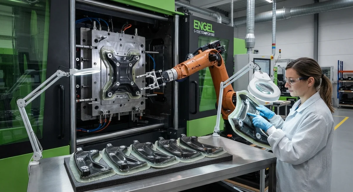
Thermoplastic overmolding of carbon fiber composites with integrated metal inserts represents a transformative manufacturing approach for multi-material structural components. This article examines process parameters, design guidelines, mechanical performance data, and applications across automotive, aerospace, and industrial sectors.
Introduction to Thermoplastic Overmolding with Carbon Fiber
Thermoplastic overmolding is an injection molding process in which a thermoplastic material is molded over a pre-placed substrate—in this case, a carbon fiber reinforced thermoplastic (CFRTP) laminate or a metal insert—to produce a single integrated component. The process combines the high specific strength and stiffness of continuous carbon fiber composites with the design flexibility and localized reinforcement of injection molded features such as ribs, bosses, snap-fits, and threaded inserts.
For B2B manufacturers in the aerospace, automotive, and industrial equipment sectors, thermoplastic overmolding with metal inserts offers a compelling value proposition: reduced part count, elimination of secondary assembly operations, improved structural performance at weight-optimized interfaces, and compatibility with high-volume production cycles. Unlike traditional adhesive bonding or mechanical fastening, overmolding creates a unified component in a single manufacturing step, reducing both direct labor costs and the quality control burden associated with multi-step assembly processes.
Process Fundamentals
Melt Impregnation and Bonding Mechanisms
The quality of the bond between the carbon fiber substrate and the overmolded thermoplastic depends on several physical and chemical mechanisms. When the molten thermoplastic resin contacts the substrate surface, three primary bonding mechanisms occur:
- Mechanical interlocking: The molten polymer flows into surface asperities and micro-porosities on the substrate, forming mechanical anchors upon solidification. The effectiveness of this mechanism depends on the viscosity of the overmolding material and the surface roughness of the insert.
- Thermal fusion bonding: When the substrate surface temperature exceeds the melting temperature (Tm) of the overmolding polymer, a true fusion bond forms across the interface. Maintaining the substrate above the matrix crystallization temperature (Tc) during injection is critical for achieving this bond.
- Chemical adhesion: Compatible polymer chemistries at the interface promote chain entanglement and, in some cases, covalent bonding. Compatibilizers and coupling agents can be applied to the insert surface or compounded into the overmolding resin to enhance chemical adhesion forces.
Critical Process Parameters
| Parameter | PA6-CF30 / Steel Insert | PA66-CF40 / Aluminum Insert | PEEK-CF30 / Titanium Insert | PP-CF20 / Brass Insert |
|---|---|---|---|---|
| Substrate preheat temperature (°C) | 200–230 | 240–270 | 340–380 | 150–180 |
| Melt temperature (°C) | 250–280 | 290–320 | 370–400 | 200–230 |
| Mold temperature (°C) | 80–120 | 100–140 | 160–200 | 40–60 |
| Injection pressure (bar) | 600–1,200 | 800–1,500 | 1,000–1,800 | 400–800 |
| Injection speed (mm/s) | 50–200 | 50–150 | 30–100 | 100–300 |
| Packing pressure (bar) | 400–800 | 600–1,000 | 700–1,200 | 300–600 |
| Cooling time (s) | 15–30 | 20–40 | 30–60 | 10–20 |
| Cycle time (s) | 40–60 | 50–80 | 70–120 | 25–45 |
Note: PA6-CF30 denotes polyamide 6 with 30% carbon fiber reinforcement by weight. Values are guidelines; specific parameters must be validated through design of experiments.
Metal Insert Design Guidelines
Insert Surface Preparation
- Mechanical abrasion: Grit blasting with 60–120 mesh alumina at 3–6 bar pressure creates consistent surface roughness (Ra 1.5–3.0 μm).
- Chemical etching: Acid-based etching creates micro-porous surface structures that enhance mechanical interlocking.
- Laser structuring: Nanosecond or picosecond laser ablation creates deterministic surface patterns with feature sizes of 10–100 μm.
- Plasma treatment: Atmospheric pressure plasma treatment activates the metal surface by introducing polar functional groups.
Insert Geometry Optimization
- Knurling: Diamond or straight knurling patterns with 0.3–1.0 mm pitch and 0.2–0.5 mm depth
- Undercuts and grooves: Circumferential grooves with 0.5–2.0 mm depth create form-locking features
- Through-holes: Perforations allow thermoplastic to flow through, creating mechanical through-anchors
- Flanges and collars: Enlarged features distribute stress over a wider area
Mechanical Performance Data
- Pull-out force: 2–5× higher than press-fit or adhesive-bonded inserts of equivalent size
- Torque retention: 85–95% of initial tightening torque after 1,000 thermal cycles (−40°C to +120°C)
- Fatigue life: 10× longer than adhesive-bonded joints at equivalent load levels
- Sealing performance: Leak-tight at 10 bar differential pressure
- Weight reduction: 30–50% compared to all-metal components
Material Selection Considerations
Selecting the appropriate combination of carbon fiber substrate, overmolding polymer, and metal insert material is critical to achieving desired performance targets. PA6 and PA66 matrices offer the best balance of mechanical performance and processability for automotive applications, with good chemical resistance to common automotive fluids such as engine oil, coolant, and brake fluid. PEEK and PEKK matrices are preferred for aerospace applications requiring continuous service temperatures above 150°C, while PP-based systems offer the most cost-effective solution for consumer and industrial products where thermal demands are moderate.
The carbon fiber reinforcement form also plays a significant role. Continuous fiber woven fabrics (2×2 twill, plain weave, or satin weave) provide maximum structural performance in the substrate, while discontinuous chopped fiber compounds (20–40% fiber by weight) are used in the overmolding material for shrinkage matching and coefficient of thermal expansion (CTE) gradient management across the metal-composite interface.
Industrial Applications
Automotive: Lightweight Structural Assemblies
The automotive industry has been an early adopter of carbon fiber thermoplastic overmolding with metal inserts for components such as front-end modules, pedal brackets, instrument panel cross-beams, and battery enclosure frames. A front-end module produced using this process achieves a 40% weight reduction compared to a stamped steel design while meeting all crash load requirements. Electric vehicle battery enclosure frames benefit particularly from the combination of thermal management capability—metal inserts conduct heat from battery cells into the carbon fiber structure—and structural rigidity with lightweight construction.
Aerospace: Bracket and Fitting Applications
Aerospace applications benefit from the combination of high-temperature thermoplastics (PEEK, PEKK) with titanium inserts for structural brackets, clevis fittings, and attachment lugs. The overmolding process eliminates the need for secondary drilling and riveting operations, reducing manufacturing cost by up to 30% while improving joint reliability through the elimination of stress concentrations associated with mechanical fasteners. Several Tier 1 aerospace suppliers have qualified overmolded carbon fiber brackets for interior and secondary airframe structures on current-generation commercial aircraft programs.
Industrial Equipment: Hydraulic and Pneumatic Components
In industrial equipment, overmolded carbon fiber components with metal inserts are being adopted for lightweight actuator housings, robotic arm end-effector interfaces, and high-speed pick-and-place machine components. The combination of reduced inertia from carbon fiber construction with the wear resistance and threaded connection capabilities of metal inserts allows significant cycle time improvements in automated manufacturing lines. Overmolded carbon fiber hydraulic cylinder end-caps, for example, reduce reciprocating mass by 50% compared to equivalent steel components, enabling higher operating speeds with lower energy consumption.
Frequently Asked Questions
Question 1: What is the maximum metal insert size that can be reliably overmolded?
Practical considerations limit most production applications to inserts with maximum cross-sectional dimensions of 200 mm × 100 mm and a maximum thickness of 15 mm. Larger inserts require specialized handling equipment and significantly extend cycle times. Finite element analysis of mold filling is recommended for large inserts.
Question 2: How does CTE mismatch affect overmolding quality?
CTE values: carbon fiber composites (longitudinal) 0–5 ppm/°C, aluminum 23 ppm/°C, steel 11–13 ppm/°C, titanium 9 ppm/°C. During cooling, the metal insert contracts more than the composite, generating beneficial residual compressive stress. Excessive mismatch can cause composite cracking. Titanium inserts offer the closest CTE match.
Question 3: What NDT methods are available for overmolded insert joints?
Validated methods include: ultrasonic testing (10–20 MHz phased array), computed tomography (5–50 μm resolution), thermographic testing, and laser shearography. A combination of in-mold cavity pressure monitoring and post-mold ultrasonic testing is recommended for production QA.
Conclusion
Thermoplastic overmolding with carbon fiber materials and integrated metal inserts achieves weight reductions of 30–50% compared to conventional all-metal designs while improving structural performance. The process is particularly well-suited to medium-to-high volume production of structural components that require threaded connections, bearing surfaces, or electrical conductivity at discrete locations. YongXian CarbonFiber supplies high-quality chopped and milled carbon fiber grades for thermoplastic compounding, as well as continuous carbon fiber fabrics sized for polyamide, polypropylene, and high-temperature thermoplastic matrix systems. Contact our engineering team for material selection guidance and process development support for your specific multi-material component design.
Part of topic
Related Articles
- Bio-Based Carbon Fiber Precursors: Lignin and Polyethylene for Low-Cost Production
- Large-Tow Carbon Fiber Cost Analysis: 48K vs 60K Price-Performance Comparison
- Carbon Fiber-Resin Interface Bonding: Surface Treatment and Coupling Agent Optimization
- Digital Twin for Carbon Fiber Manufacturing: Real-Time Process Monitoring and Defect Prevention
- Thermoplastic Carbon Fiber Welding for Automotive: Ultrasonic and Induction Welding Process Windows
- Large-Tow Carbon Fiber Wet Spinning: Process Optimization for 48K/60K Production Efficiency
Interested in Our Products?
Contact our team for competitive pricing and technical specifications.
Get a QuoteRelated Products

Carbon fiber standard plate-3k stripe
Lightweight, ultra-rigid standard sheets for drone fuselages, robot housings, facades and structural applications.

Carbon Fiber Plate — 3K Twill T700 1.5mm
Thin 1.5mm carbon fiber plate with 3K twill weave surface. Lightweight and stiff, commonly used for covers, panels, drone bodies, and applications requiring a premium aesthetic appearance.

Square Carbon Fiber Tube — 3K Twill T700
Square cross-section carbon fiber tube manufactured with 3K twill weave for torsional strength. Preferred for structural frames, trusses, and support columns where rectangular geometry offers design flexibility.

Carbon Fiber Plate — 3K Twill T700 3.0mm
Medium-thickness 3.0mm carbon fiber plate offering significantly higher load capacity while maintaining attractive 3K twill finish. Suitable for structural brackets, reinforcement plates, and load-bearing panels.

Carbon Fiber Plate — UD Unidirectional T700
Unidirectional carbon fiber plate with all fibers oriented in a single direction for maximum strength along the fiber axis. Essential for structural reinforcements, splints, and applications where load direction is predictable.