
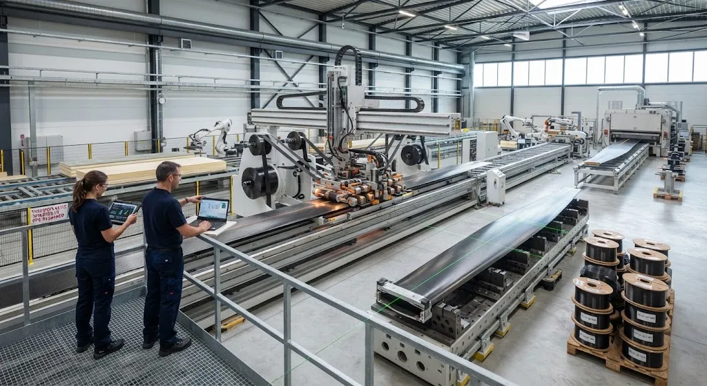
Blade manufacturing is one of the last largely manual steps in wind turbine production. A thermoset blade of 100 meters needs hundreds of hours of hand layup, a multi-hour curing cycle in an oversized mold, and a workforce that scales with global blade demand. For factories in high-wage
Introduction
Blade manufacturing is one of the last largely manual steps in wind turbine production. A thermoset blade of 100 meters needs hundreds of hours of hand layup, a multi-hour curing cycle in an oversized mold, and a workforce that scales with global blade demand. For factories in high-wage countries, the labor content is the decisive cost disadvantage: the same blade that costs one number to build in a region with lower wages costs a multiple in Central Europe or the United States, and the gap has pushed most blade production toward low-cost regions over the past decade.
The Thermo-Blade-Spine project, a joint effort of three Fraunhofer institutes running through March 2027, attacks this economics problem at the architecture level. Instead of a thermoset laminated shell built around a discrete spar cap, the blade is organized around a continuous thermoplastic spine — a welded load-bearing backbone — with sandwich panels attached around it. The combination of the CONTIjoin tape-welding process, wide thermoplastic UD tapes and automated sandwich assembly removes the curing cycle, removes trimming scrap and removes the manual layup that dominates thermoset cost. An 18-meter demonstration shell is now in validation at the IWES BladeMaker DemoCenter, providing the first industrial-scale evidence for the concept. This article explains how the architecture works, what the automation line looks like, and whether the economics hold up in high-wage environments.
The Spine Architecture
The name describes the structural logic. In a conventional thermoset blade, the main load path is a spar cap laminated inside an aerodynamic shell; the assembly is a single bonded and consolidated structure. The Thermo-Blade-Spine concept separates the two functions cleanly. A continuous thermoplastic spine — built up by welding layers of UD tape onto a central laminate — carries the bending and compression loads along the blade length. Around it, sandwich shells, consisting of thermoplastic face sheets over a lightweight core, are attached to form the aerodynamic envelope. The spine is the strength; the shell is the shape.
This separation creates the manufacturing advantage. The spine is a straight, axisymmetric build-up job that suits an automated in-line welding process perfectly: feed tape, heat, consolidate, advance. The sandwich shells are flat or gently curved panels that can be produced on automated panel lines rather than in giant closed molds. And because every component is thermoplastic, all of them can be welded together at the end — no adhesive curing wait, no vacuum bagging, no autoclave.
How the Automated Line Runs
The production line reads as a sequence of automated stations rather than a series of manual workbenches:
- Spine welding line: the CONTIjoin process, developed at Fraunhofer IWS, feeds pre-consolidated thermoplastic UD tapes through a welding head that heats, presses and consolidates each layer onto the growing spine in one continuous pass, replacing manual spar cap layup and its curing cycle.
- Wide tape supply: Fraunhofer IMWS supplies UD tapes up to ten times wider than standard 25-50 mm strips, cutting the number of passes across the spine width by an order of magnitude and reducing weld-seam density in the load path.
- Sandwich panel line: face sheets and core are assembled and consolidated on automated panel equipment, producing the shell elements in parallel with spine build-up rather than sequentially in one mold.
- Final welding and assembly: shells are welded to the spine and to each other in a final consolidation step, joining the structure without adhesive cure time and without closing a full-length mold over the finished part.
The line is deliberately modular: each station runs continuously, buffer stock between stations decouples their rates, and a fault in one station stops that station rather than the whole blade. This is the same logic that industrial automation applies to joining and assembly in other sectors, and it is precisely what manual blade fabrication never achieved.
Economics of High-Rate Production in High-Wage Countries
The economic case rests on replacing labor hours and cycle time with capital and energy. The table below compares a representative thermoset blade line against the Thermo-Blade-Spine automation concept for a 75-90 meter onshore blade:
| Parameter | Thermoset Manual Line | Thermo-Blade-Spine Automated Line |
|---|---|---|
| Direct labor per blade | 1,800-2,600 hours | 250-400 hours |
| Curing cycle per component | 4-8 hours (infusion + cure) | None (consolidated on the line) |
| Scrap and trim waste | 15-25 percent of material | Near zero (offsets re-consolidated) |
| Floor space for molds | Full-length mold per size | Panel lines + spine line, shared sizes |
| Throughput sensitivity to wages | High (labor-dominated) | Low (capital-dominated) |
| Energy per blade | High (heated molds, HVAC) | Moderate (welding heads only) |
The numbers are the point: when labor content falls by roughly 85 percent, the wage differential between regions stops being the deciding factor. The capital cost of the automation is high, but it amortizes across the full production program, and the line's rate is set by machine speed rather than operator headcount. For a factory in Germany, Denmark or the United States, the model converts a structural labor-cost disadvantage into a capital-investment decision — the same transition other manufacturing sectors made decades ago.
Zero-Waste and End-of-Life
Thermoplastic processing changes the waste equation at every stage. In thermoset manufacturing, trimming a cured laminate generates scrap that cannot be reused, mold flash and bagging consumables go to landfill, and rejected parts carry the full cost of their fiber. In a welding-based process, offcuts and mis-consolidated sections are simply fed back through the welding head — the material is a thermoplastic, so it can be re-melted and re-consolidated until it becomes part of a component. Process scrap approaches zero, which matters doubly when carbon fiber is the expensive input.
End-of-life follows the same logic. A welded thermoplastic blade is not a cured monolith with fibers locked in a crosslinked matrix; it is a structure whose matrix can be re-melted and whose components can be separated at the weld lines. At decommissioning, the blade can be disassembled into spine and panels, the sandwich core separated from the face sheets, and the fiber recovered for re-use. For blades that will be recycled under tightening European waste rules, this is not an environmental optional extra — it is becoming a design requirement, and the weld-based architecture is one of the few that meets it natively.
The 18-Meter Demonstrator at IWES BladeMaker DemoCenter
Validation is running on an 18-meter demonstration shell at the IWES BladeMaker DemoCenter. The demonstrator is scaled to test the full process chain rather than a single station, and the current validation scope covers:
| Validation Item | What Is Being Proven |
|---|---|
| Spine welding integrity | Seam quality and load-path continuity over a continuous 18 m build |
| Sandwich shell production | Panel rates, core-to-face bonding and dimensional accuracy |
| Final welding of shell to spine | Joint strength of the spine-shell weld line |
| Zero-waste loop | Re-consolidation of offcuts at production-representative rates |
| Cycle time model | Measured line rate versus the economic model assumptions |
The 18-meter scale is small enough to iterate quickly and large enough to expose the problems that appear only when a process runs as a continuous line — feed stability over long runs, thickness build-up tolerances, and the thermal management of a welding head traversing a growing laminate. These are precisely the failure modes that would otherwise surface, expensively, on a full-length blade.
Pathway to 2027
The project runs through March 2027, with the demonstrator work now feeding the industrialization roadmap. Three open questions will decide whether the concept moves to commercial lines. First, rate: the measured line speed must beat the manual baseline at full scale, including the sandwich panel line's contribution, before the capital case closes. Second, fatigue: the welded spine-shell joint needs cycle data at blade-relevant loads, because joint fatigue is where welded thermoplastic structures have historically been challenged. Third, cost: the blended cost of wide tape supply and welding energy must stay below the avoided labor and scrap cost. The 18-meter demonstrator is producing exactly the data needed to answer all three, and the answers will determine whether the first commercial Thermo-Blade-Spine lines break ground before the end of the decade.
Frequently Asked Questions
What makes the Thermo-Blade-Spine architecture different from a conventional thermoset blade?
A conventional blade is a laminated thermoset shell built around a discrete spar cap: hand layup, vacuum bagging, infusion and a multi-hour cure in a full-length mold. The Thermo-Blade-Spine blade separates the load path from the aero shell: a continuous thermoplastic spine built by welding UD tape layers carries the loads, and sandwich shells are welded around it to form the envelope. The difference is manufacturing: no curing cycle, no bagging consumables, near-zero scrap and mostly automated assembly, which changes the cost structure of blade production in high-wage countries.
How does thermoplastic processing achieve zero waste?
Thermoplastic matrices can be re-melted and re-consolidated. Offcuts from trimming, mis-consolidated sections and rejected build-ups are fed back through the welding line instead of being discarded, so process waste approaches zero. Because the blade is welded rather than cured, components can also be separated at the weld lines at end of life, the sandwich core removed from the face sheets, and the fiber recovered for reuse — an advantage that thermoset blades, with their crosslinked and irreversibly cured matrix, do not have.
Is automated thermoplastic blade production cost-competitive in high-wage countries?
The economics work by removing the dominant cost item: manual labor. Automated thermoplastic lines reduce direct labor per blade by roughly 85 percent relative to manual thermoset fabrication, and they eliminate curing cycle time and trimming scrap. The capital investment replaces labor content, so the wage differential between regions stops being decisive. The open questions are line rate, joint fatigue performance and tape cost, which the 18-meter demonstrator at the IWES BladeMaker DemoCenter is currently measuring; if those three hold, the automation model becomes the cheaper route in high-wage environments.
Conclusion
The Thermo-Blade-Spine project is a direct answer to the question that has shaped blade manufacturing for a decade: can high-wage countries produce blades competitively, or is the industry permanently committed to low-cost regions? By organizing the blade around a welded thermoplastic spine, the concept removes the three cost drivers that manual thermoset production cannot escape — labor hours, curing cycles and scrap. The 18-meter demonstrator at IWES BladeMaker DemoCenter is now validating the line against the economic model, and the project's March 2027 conclusion will show whether the first commercial automated lines are feasible. For blade programs and material suppliers, the direction is already clear: the competitive question is shifting from wages to automation.
For engineers evaluating thermoplastic blade and spar-cap material systems, review our carbon fiber tape and reinforcement product range, or contact our engineering team to discuss fiber formats, tape supply and qualification support for automated blade programs.
Part of topic
Related Articles
- Bio-Based Carbon Fiber Precursors: Lignin and Polyethylene for Low-Cost Production
- Large-Tow Carbon Fiber Cost Analysis: 48K vs 60K Price-Performance Comparison
- Carbon Fiber-Resin Interface Bonding: Surface Treatment and Coupling Agent Optimization
- Digital Twin for Carbon Fiber Manufacturing: Real-Time Process Monitoring and Defect Prevention
- Thermoplastic Carbon Fiber Welding for Automotive: Ultrasonic and Induction Welding Process Windows
- Large-Tow Carbon Fiber Wet Spinning: Process Optimization for 48K/60K Production Efficiency
Interested in Our Products?
Contact our team for competitive pricing and technical specifications.
Get a QuoteRelated Products
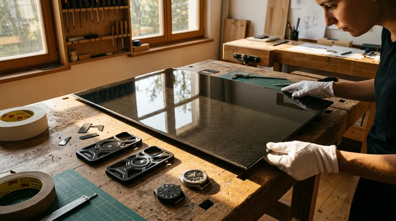
Carbon Fiber Plate — High-Gloss Decorative
High-gloss decorative carbon fiber plate with a mirror-like surface finish. The glossy coating enhances the visible 3K twill weave, creating a premium aesthetic for consumer-facing applications. Lightweight yet stiff, available in thin gauges for easy cutting and forming.
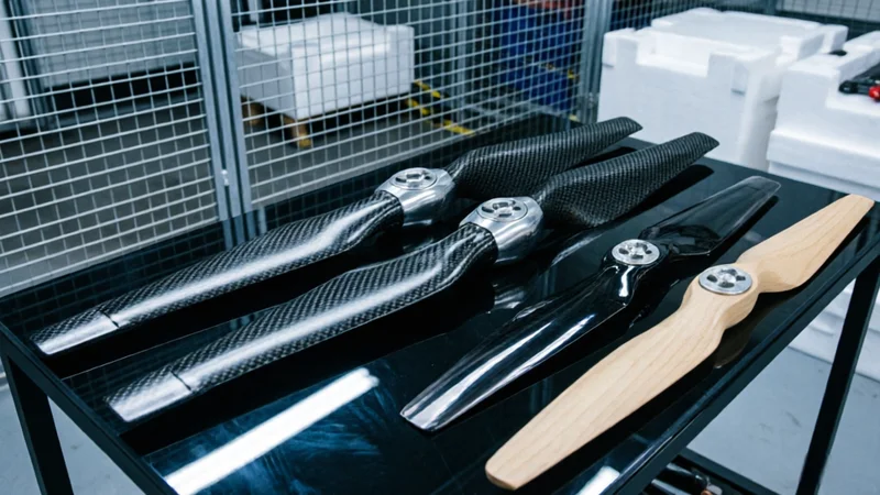
Carbon Fiber Drone Propeller — High-Performance Prepreg Molded
Prepreg-molded carbon fiber propellers for industrial and racing drones. Optimized airfoil design with balanced blade geometry for maximum thrust efficiency. 3-5× stiffer than nylon/plastic props, reducing blade flutter and improving flight stability. Available in common sizes or custom diameter/pitch.