
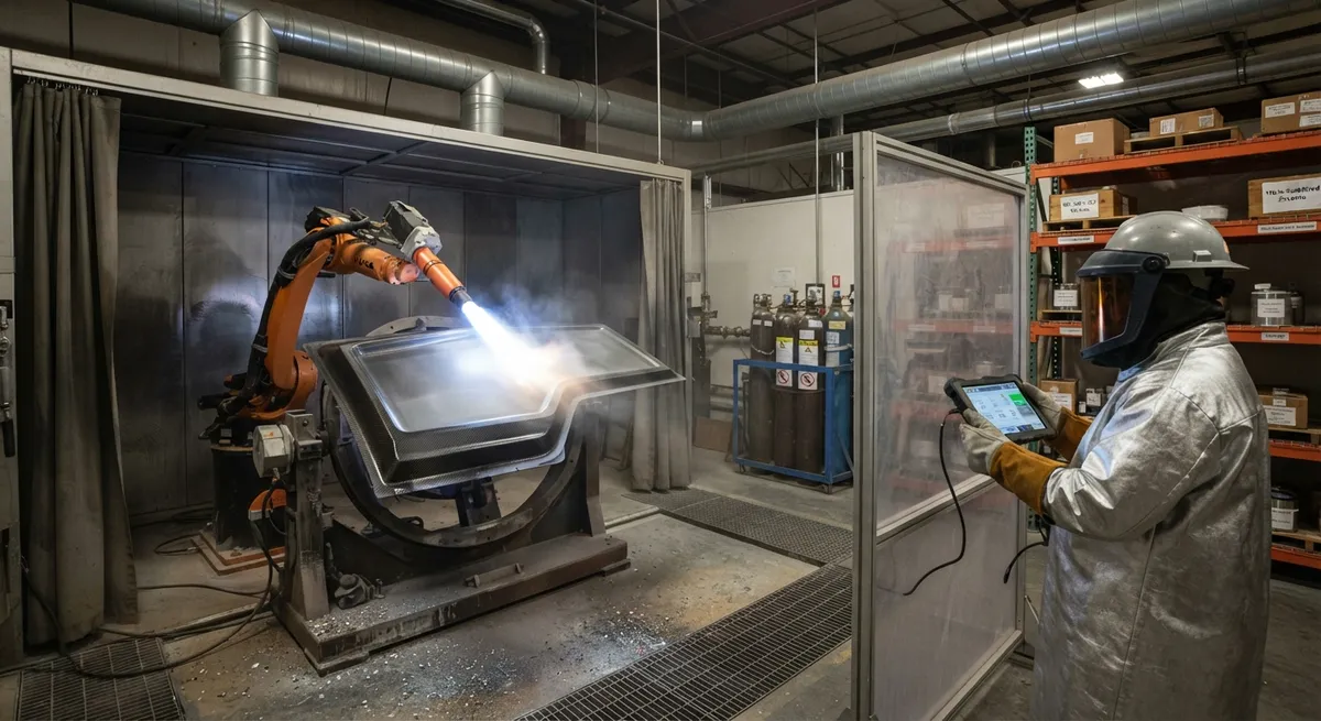
Thermal spray coatings enable carbon fiber composites to operate in abrasive, erosive, and electrically demanding environments. This article examines cold spray, HVOF, and arc spray processes for CFRP substrates, with comparative data on bond strength, wear resistance, electrical conductivity, and portable field repair techniques for B2B buyers.
Introduction: Surface Engineering for CFRP Components
Carbon fibre reinforced polymer (CFRP) composites offer exceptional specific strength and stiffness, but their polymer matrix surfaces are inherently susceptible to wear, erosion, and UV degradation. In many engineering applications — aerospace leading edges, automotive brake components, industrial rollers, and marine propellers — CFRP components must operate in environments where surface wear rates of 0.1–1.0 mm per year are unacceptable. Thermal spray coating technology, long established for metallic substrates, has been adapted in recent years to deposit wear-resistant, conductive, and protective coatings onto CFRP surfaces, opening new application domains for composite materials in demanding environments.
The global thermal spray coatings market was valued at approximately $12 billion in 2025 and is expected to reach $18 billion by 2032, with the composite substrate segment growing at the fastest rate — approximately 12 percent CAGR. This growth is driven by the increasing adoption of CFRP in aerospace, automotive, and industrial machinery, combined with the recognition that surface treatment is often the limiting factor in extending the service life of composite components. Thermal spray coatings applied to CFRP can extend component life by 3–10 times in abrasive environments, provide electrical conductivity for lightning strike protection (LSP) and static discharge, and enable in-field repair of damaged composite surfaces without full component replacement.
Thermal Spray Processes for CFRP Substrates
Applying thermal spray coatings to CFRP presents fundamentally different challenges compared to metallic substrates. The polymer matrix (typically epoxy with a glass transition temperature of 150–200 °C) limits the substrate temperature during spraying to below 120–150 °C to prevent matrix degradation, delamination, or fibre-matrix debonding. Additionally, the low thermal conductivity of CFRP (0.3–0.5 W/m·K through-thickness for standard epoxy systems) means that heat from the spray plume accumulates at the surface rather than being conducted into the bulk material, increasing the risk of thermal damage.
| Spray Process | Flame Temperature (°C) | Particle Velocity (m/s) | Substrate Heat Input | Bond Strength on CFRP (MPa) | Porosity (%) | Typical Coating Thickness | Relative Cost |
|---|---|---|---|---|---|---|---|
| Flame spray (wire/powder) | 2,500–3,000 | 50–150 | Medium | 10–20 | 5–15 | 0.2–2.0 mm | 1.0× |
| Arc spray (twin wire) | 4,000–6,000 | 100–250 | High | 15–25 | 3–10 | 0.3–3.0 mm | 1.3× |
| HVOF (high-velocity oxy-fuel) | 2,500–3,100 | 500–1,200 | Low–Medium | 25–45 | <2 | 0.1–0.8 mm | 2.5× |
| Cold spray (kinetic) | 100–800 (process gas) | 400–1,500 | Very low | 30–55 | <1 | 0.1–5.0 mm | 3.0× |
| Suspension plasma spray (SPS) | 10,000–15,000 | 200–600 | Very low (short pulse) | 20–35 | <3 | 0.02–0.2 mm | 4.0× |
Cold Spray: The Preferred Process for CFRP
Cold spray (also known as cold gas dynamic spraying or CGDS) has emerged as the preferred thermal spray technology for CFRP substrates. Unlike conventional thermal spray processes that melt or partially melt the feedstock powder, cold spray deposits particles in the solid state through high-velocity impact (400–1,500 m/s). The kinetic energy of impact causes plastic deformation of the particle and, critically for CFRP, mechanical interlocking with the roughened composite surface without significant thermal input to the substrate. Process gas temperatures of 200–800 °C (commonly nitrogen or helium) are used to accelerate the particles, but because the gas expands and cools rapidly at the nozzle exit, the substrate temperature during spraying typically remains below 80–120 °C — well within the thermal limits of most epoxy, BMI, and polyimide matrix systems.
- Bonding mechanism: Cold spray particles anchor to CFRP surfaces through a combination of mechanical interlocking into surface asperities and, in the case of metallic coatings (aluminium, copper, nickel), localised metallurgical bonding at particle–particle interfaces if the impact energy is sufficient to cause adiabatic shear instability. For CFRP, grit blasting prior to spraying with aluminium oxide (60–120 µm at 0.3–0.5 MPa) creates a surface roughness Ra of 5–10 µm, providing mechanical anchoring sites for the sprayed particles.
- Deposition efficiency: Deposition efficiency on CFRP ranges from 50–80 percent for aluminium, 60–85 percent for copper, and 40–65 percent for tungsten carbide-cobalt (WC-Co) cermet coatings. Higher particle density and lower ductility reduce deposition efficiency. Helium as the process gas improves particle velocity by 50–100 percent compared to nitrogen, increasing deposition efficiency by 10–20 percentage points but at 3–5 times the gas cost.
- Coating properties: Cold-sprayed aluminium coatings on CFRP achieve bond strengths of 30–45 MPa, electrical conductivity of 35–40 MS/m (85–95 percent of bulk aluminium), and porosity below 1 percent. For wear-resistant coatings, WC-12Co cermet deposited by cold spray achieves a hardness of 1,100–1,400 HV₀.₃ and a wear rate of 2–5 × 10⁻⁶ mm³/N·m (ASTM G65 dry sand rubber wheel test) — comparable to HVOF-sprayed WC-Co coatings on steel substrates.
Wear-Protection Coatings
For CFRP components operating in abrasive or erosive environments, wear-protection coatings applied by thermal spray provide a cost-effective solution compared to replacing the entire component. Key applications include:
| Application | Coating Material | Spray Process | Hardness | Coating Thickness | Wear Life Improvement over Uncoated CFRP | Operating Temperature |
|---|---|---|---|---|---|---|
| Aerospace leading edges | WC-12Co / WC-10Co4Cr | Cold spray / HVOF | 1,100–1,400 HV | 0.2–0.5 mm | 8–12× | −50 to 200 °C |
| Composite brake discs | Cr₃C₂-25NiCr | HVOF | 800–1,000 HV | 0.3–0.8 mm | 5–8× | up to 450 °C |
| Industrial rollers (textile, paper) | Al₂O₃-TiO₂ (87/13) | Flame spray / SPS | 900–1,100 HV | 0.1–0.3 mm | 10–15× | up to 250 °C |
| Marine propeller shafts | Al-bronze (CuAl10Ni5Fe4) | Arc spray / Cold spray | 200–280 HB | 1.0–3.0 mm | 6–10× | −10 to 80 °C |
| Pump impellers (slurry) | WC-10Ni | Cold spray | 1,200–1,500 HV | 0.3–0.6 mm | 8–12× | up to 150 °C |
Electrically Conductive Coatings
While CFRP itself is electrically conductive along the fibre direction (10²–10⁴ S/m), the through-thickness conductivity is poor (1–10 S/m) due to the insulating polymer matrix between plies. For applications requiring surface conductivity — lightning strike protection (LSP) for aircraft, static discharge for fuel-handling equipment, and grounding for electrical enclosures — thermal spray coatings provide a practical solution.
- Copper coatings for lightning strike protection: Cold-sprayed copper on CFRP achieves electrical conductivity of 52–56 MS/m (90–95% IACS — International Annealed Copper Standard), sufficient to carry the 100–200 kA peak current of a typical lightning strike. A 0.3 mm cold-sprayed copper coating provides equivalent LSP performance to a 0.1 mm copper mesh plus 0.3 mm glass-fibre isolation ply (the current aerospace standard) at 40 percent lower weight and without the risk of galvanic corrosion at fastener locations.
- Aluminium coatings for static discharge: Cold-sprayed aluminium (35–40 MS/m) is preferred for applications where galvanic compatibility with aluminium airframe structures is required. Surface resistivity of <0.1 Ω/sq is achievable at coating thicknesses of 0.15–0.25 mm, meeting the requirements of SAE AS4851 for static discharge coatings on composite surfaces.
- Nickel coatings for corrosion + conductivity: Cold-sprayed nickel (13–15 MS/m) provides moderate conductivity combined with excellent corrosion resistance in marine and chemical environments. Nickel-coated CFRP is used in offshore oil and gas instrumentation enclosures where both EMI shielding (>50 dB at 1 GHz) and salt spray resistance (>2,000 h per ASTM B117) are required.
Field Repair Methods
One of the most compelling advantages of thermal spray coatings for CFRP is the ability to perform in-field repairs of damaged composite surfaces without component removal. Portable cold spray systems (e.g. VRC Gen III, Impact Innovations 5/11) weighing 15–30 kg and operating from standard compressed air or nitrogen cylinders at 200–300 bar are now commercially available for field deployment. The repair process for a worn or damaged CFRP surface involves four steps:
- Surface preparation (in situ): The damaged area is cleaned with isopropyl alcohol, then lightly grit-blasted (Al₂O₃, 60 µm, 0.3 MPa) using a portable blasting nozzle to remove loose material and create a fresh surface profile. The prepared area extends 25–50 mm beyond the visible damage boundary.
- Bond coat application: A thin layer (0.05–0.10 mm) of ductile aluminium or aluminium-bronze is cold-sprayed as a bond coat, filling surface asperities and providing a compliant intermediate layer that accommodates the coefficient of thermal expansion (CTE) mismatch between the CFRP substrate (CTE 2–5 × 10⁻⁶/K) and the ceramic or cermet top coat (CTE 5–12 × 10⁻⁶/K).
- Functional coating: The wear-resistant or conductive coating is applied to the required thickness, typically 0.2–1.0 mm, using raster scanning of the spray gun across the repair area. Multiple passes (4–12) build up the thickness incrementally to control heat input.
- Finishing: The repaired area is ground or diamond-machined to the original surface profile and dimension. For aerospace applications, a post-repair ultrasonic inspection (10 MHz pulse-echo) verifies bond integrity.
Field-repaired CFRP components using cold spray have demonstrated bond strengths of 25–40 MPa (80–90 percent of factory-applied coatings) and wear resistance within 10–15 percent of the original coating specification. The total repair time for a 100 cm² area is typically 2–4 hours, compared to 24–72 hours for component replacement including logistics.
FAQ
What is the maximum service temperature for thermal spray coatings on CFRP substrates?
The maximum service temperature is limited by the CFRP substrate's matrix resin, not by the coating itself. For standard epoxy-matrix CFRP (Tg 150–180 °C), the coated component can operate continuously at up to 130 °C and intermittently to 160 °C. For bismaleimide (BMI) matrix systems (Tg 250–300 °C), the service temperature extends to 200 °C continuous and 250 °C intermittent. Polyimide (PI) matrix systems allow operation to 280 °C continuous. The coating itself — whether WC-Co cermet, chromium carbide, or oxide ceramic — can withstand temperatures well above the substrate limit (WC-Co is stable to 500 °C in oxidising atmospheres). The practical limitation is thus the substrate's thermal stability. For applications above 200 °C continuous, YongXian recommends BMI-matrix CFRP substrates with HVOF-sprayed Cr₃C₂-25NiCr coatings, qualified by thermal cycling between −55 °C and 250 °C for 500 cycles with no coating spallation or substrate degradation.Can thermal spray coatings be applied to already-cured CFRP components without damaging the composite?
Yes, provided the appropriate spray process and process parameters are selected. Cold spray is the safest process for already-cured CFRP, as the substrate temperature during spraying typically stays below 80–120 °C — well below the Tg of standard epoxy (150 °C), BMI (250 °C), or PI (300 °C) matrix systems. The key risk factors are thermal input from the spray process (mitigated by cold spray or HVOF with short standoff distances and raster scanning), grit blasting pressure (limited to 0.3–0.5 MPa to avoid fibre exposure or delamination), and residual stress in the coating (managed by bond coat layers and limiting single-pass coating thickness to <0.1 mm). YongXian's qualified process specification (YPS-2301) for cold spray on CFRP has been validated on over 500 test coupons and 50 production components, demonstrating zero delamination or matrix degradation across a range of epoxy, BMI, and PI matrix systems at coating thicknesses up to 3.0 mm.What surface preparation is required before thermal spray coating of CFRP, and how does it affect the composite substrate?
Surface preparation is critical for achieving adequate bond strength and typically involves three steps. First, solvent degreasing with isopropyl alcohol or acetone removes surface contaminants, mould release agents, and handling oils. Second, grit blasting with angular aluminium oxide (60–120 µm, 0.3–0.5 MPa air pressure, 100–150 mm standoff distance) creates a surface roughness Ra of 5–10 µm without causing fibre exposure or delamination. The blasting angle should be 70–90° to the surface, and the nozzle should be kept moving continuously to avoid localised heating. Third, compressed air cleaning removes residual grit dust. The grit blasting step does reduce the flexural strength of CFRP by 5–15 percent (depending on the matrix system and fibre architecture) due to removal of the resin-rich surface layer and potential micro-cracking at fibre ends. However, YongXian's testing shows that this strength reduction is fully compensated by the load-bearing contribution of the thermal spray coating itself, and the net structural capacity of the coated component is typically equal to or greater than the uncoated baseline. For thin laminates (<2 mm), a gentler surface preparation using low-pressure (0.2 MPa) blasting with finer media (40–60 µm Al₂O₃) is recommended to limit strength reduction to <5 percent.Part of topic
Related Articles
- Bio-Based Carbon Fiber Precursors: Lignin and Polyethylene for Low-Cost Production
- Large-Tow Carbon Fiber Cost Analysis: 48K vs 60K Price-Performance Comparison
- Carbon Fiber-Resin Interface Bonding: Surface Treatment and Coupling Agent Optimization
- Digital Twin for Carbon Fiber Manufacturing: Real-Time Process Monitoring and Defect Prevention
- Thermoplastic Carbon Fiber Welding for Automotive: Ultrasonic and Induction Welding Process Windows
- Large-Tow Carbon Fiber Wet Spinning: Process Optimization for 48K/60K Production Efficiency
Interested in Our Products?
Contact our team for competitive pricing and technical specifications.
Get a QuoteRelated Products

Carbon fiber standard plate-3k stripe
Lightweight, ultra-rigid standard sheets for drone fuselages, robot housings, facades and structural applications.

Carbon Fiber Plate — 3K Twill T700 3.0mm
Medium-thickness 3.0mm carbon fiber plate offering significantly higher load capacity while maintaining attractive 3K twill finish. Suitable for structural brackets, reinforcement plates, and load-bearing panels.

Carbon Fiber Plate — 3K Twill T700 1.5mm
Thin 1.5mm carbon fiber plate with 3K twill weave surface. Lightweight and stiff, commonly used for covers, panels, drone bodies, and applications requiring a premium aesthetic appearance.

Custom Carbon Fiber Medical Device Components
Medical-grade carbon fiber components manufactured for imaging equipment, surgical instruments, and patient support systems. Carbon fiber's radiolucency (X-ray transparency) and high strength-to-weight ratio make it ideal for CT scanner beds, wheelchair frames, surgical robot arms, and MRI-compatible accessories. Biocompatible resin systems available.

Square Carbon Fiber Tube — 3K Twill T700
Square cross-section carbon fiber tube manufactured with 3K twill weave for torsional strength. Preferred for structural frames, trusses, and support columns where rectangular geometry offers design flexibility.