
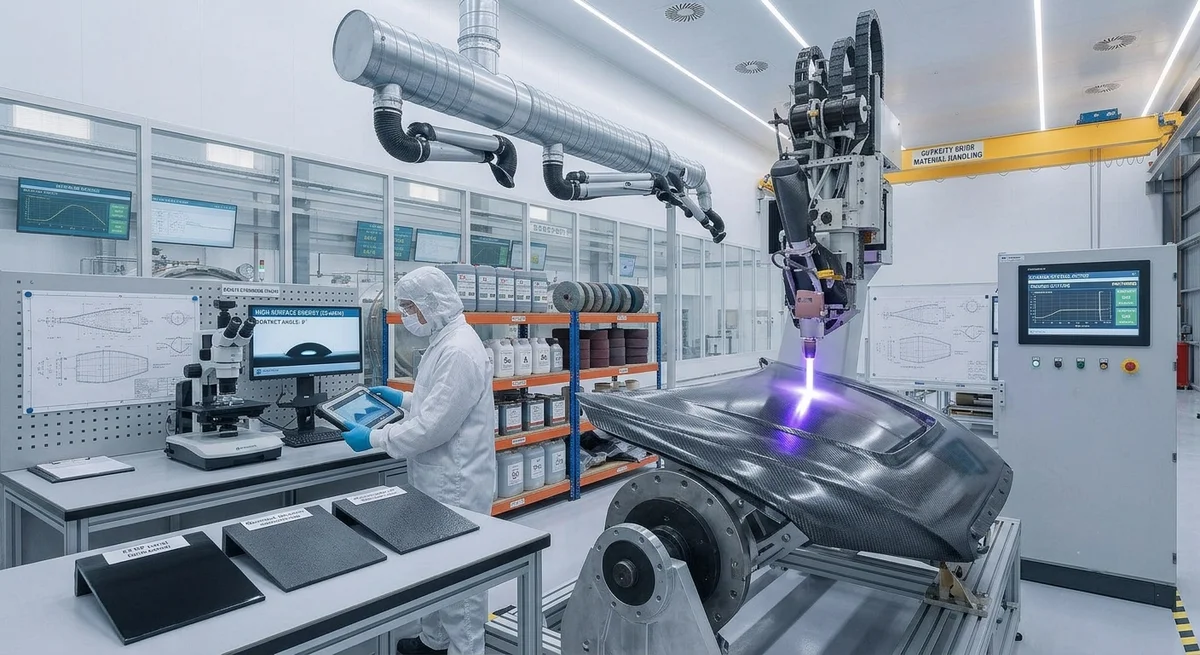
Effective surface treatment is critical for achieving strong adhesive bonds and durable paint finishes on carbon fiber composites. This article compares mechanical abrasion, plasma treatment, chemical etching, laser treatment, and primer systems, with quantitative adhesion data and process recommendations for B2B buyers.
Carbon fiber composites offer exceptional strength-to-weight ratios, but their inherently smooth, chemically inert surface presents a fundamental challenge: achieving reliable adhesion for bonding operations and paint applications. Unlike metals, whose oxide layers provide natural bonding sites, carbon fiber surfaces require deliberate modification to create mechanical interlocking sites and chemical bonding functionality. The global structural adhesives market for composites is projected to reach $6.8 billion by 2028, and surface preparation quality is the single largest variable affecting joint strength and durability.
Why Carbon Fiber Surface Treatment Matters
The carbon fiber composite surface consists of epoxy or thermoplastic matrix resin with exposed fiber ends. In its as-molded state, this surface exhibits low surface energy (typically 28-34 mJ/m²), which is insufficient for most adhesives and paints to form durable bonds. Without proper treatment, bond strengths may be only 25-40% of what the adhesive system is capable of delivering. Industry data shows that 70% of adhesive bond failures in composite structures originate from inadequate surface preparation.
| Surface Condition | Surface Energy (mJ/m²) | Lap Shear Strength (MPa) | Failure Mode |
|---|---|---|---|
| As-molded (untreated) | 28-34 | 8-12 | Adhesive (interface) |
| Hand sanding (120 grit) | 36-42 | 18-25 | Mixed (50% cohesive) |
| Grit blasting (60 mesh alumina) | 40-48 | 22-30 | Mixed (60% cohesive) |
| Atmospheric plasma | 50-68 | 28-38 | Cohesive (substrate) |
| Low-pressure plasma | 58-72 | 30-42 | Cohesive (substrate) |
| Corona discharge | 48-60 | 24-34 | Mixed (70% cohesive) |
| Chemical etching (sulfuric/peroxide) | 44-52 | 20-30 | Mixed (50% cohesive) |
| Laser ablation (UV nanosecond) | 55-70 | 28-40 | Cohesive (substrate) |
| Primer + silane coupling agent | 45-55 | 26-34 | Mixed (60% cohesive) |
Surface Treatment Methods in Detail
1. Mechanical Abrasion
Mechanical methods physically roughen the surface to increase contact area and create mechanical interlocking sites. Common techniques include:
- Hand sanding with 80-120 grit silicon carbide paper — suitable for small parts and repair work but inconsistent for production. Removes approximately 10-30 µm of surface material.
- Grit blasting with 60-100 mesh aluminum oxide or garnet at 2-4 bar pressure — consistent results for larger surface areas. Increases surface roughness (Ra) from 0.5-1.0 µm to 3.0-6.0 µm.
- Rotary abrasion with Scotch-Brite or similar non-woven abrasive pads — good for edge preparation and spot repairs.
Limitations: Risk of fiber damage if too aggressive; dust generation requires extraction; not suitable for complex geometries or internal surfaces.
2. Plasma Treatment
Plasma treatment exposes the surface to ionized gas that creates reactive functional groups (hydroxyl, carboxyl, amine) on the composite surface, dramatically increasing surface energy. Two primary configurations are used in production:
- Atmospheric plasma: Plasma jet at atmospheric pressure, suitable for in-line production. Treatment speed: 1-10 m/min. Effective width: 10-50 mm per nozzle. No vacuum chamber needed. Initial equipment cost: $30,000-80,000.
- Low-pressure (vacuum) plasma: Chamber-based process using oxygen, argon, or nitrogen plasma at 0.1-1.0 mbar. Best uniformity and highest surface energy activation. Batch processing, cycle time: 5-30 minutes. Equipment cost: $100,000-400,000.
3. Chemical Etching
Chemical methods use oxidizing acid solutions to etch the resin surface and create micro-porosity. The most common formulations include chromic acid (now largely discontinued for environmental reasons), sulfuric acid/hydrogen peroxide (piranha solution), and sodium hydroxide solutions.
Typical process: Immerse in 70% sulfuric acid / 30% hydrogen peroxide mixture at 60-80°C for 5-15 minutes, rinse thoroughly, and dry. This creates a micro-porous surface with 0.2-2.0 µm pore depth.
Limitations: Hazardous chemical handling, waste disposal costs, environmental compliance, potential fiber degradation with extended exposure.
4. Laser Ablation
Laser surface treatment uses pulsed laser energy to selectively remove the resin-rich surface layer without damaging underlying fibers. UV nanosecond lasers (355 nm, 10-30 W) are preferred for their precision and minimal heat-affected zone.
Key parameters: Pulse energy 0.5-5 mJ, scan speed 500-5000 mm/s, overlap ratio 50-80%, removal depth 5-20 µm. The process creates a precisely controlled surface texture with exposed fiber ends and micro-cavities for mechanical interlocking.
Advantages: No consumables, no chemical waste, robotic integration, consistent repeatability. Disadvantages: High capital cost ($150,000-500,000), slower throughput for large areas.
5. Primer and Coupling Agent Systems
Chemical adhesion promoters applied as a thin coating can significantly improve bond strength without mechanical surface modification. Common systems include:
- Silane coupling agents (e.g., γ-glycidoxypropyltrimethoxysilane): Applied as 0.5-2% solution in water/alcohol, forms chemical bonds between the composite surface and adhesive.
- Two-part epoxy primers: Solvent-borne or waterborne epoxy formulations that penetrate surface micro-cracks and provide a compatible bonding layer.
- Polyurethane-based adhesion promoters: For bonding to polyurethane adhesives and paints.
Process Selection Guide for B2B Buyers
| Factor | Mechanical | Plasma | Chemical | Laser | Primer |
|---|---|---|---|---|---|
| Investment (equipment) | $500-5,000 | $30K-400K | $5K-20K | $150K-500K | $1K-5K |
| Cost per part (small, 0.1 m²) | $0.10-0.50 | $0.05-0.30 | $0.15-0.60 | $0.20-1.00 | $0.30-1.50 |
| Cycle time per part | 1-5 min (manual) | 10-60 sec | 10-30 min | 5-60 sec | 5-30 min (cure) |
| Consistency (CoV %) | 15-25% | 3-8% | 8-15% | 2-5% | 10-20% |
| Suitable for automation | Moderate | Excellent | Poor | Excellent | Moderate |
| Environmental impact | Dust | Minimal | Chemical waste | Minimal | VOCs |
| Peel strength improvement vs untreated | 2-3x | 3-5x | 2-3x | 3-4x | 2-3x |
Quality Control and Verification
Verifying surface treatment quality is essential for production reliability. Standard methods include:
- Contact angle measurement: Water contact angle below 30° indicates adequate surface activation. Automated goniometers provide real-time QC at $15,000-40,000.
- Dyne test inks: Simple pass/fail test using surface energy marker pens. A 38-44 mN/m ink that wets the surface indicates sufficient treatment for most epoxy adhesives.
- FTIR spectroscopy: Identifies specific functional groups created by plasma or chemical treatment. Used for process validation rather than production QC.
- Cross-hatch adhesion test (ASTM D3359): Tape pull test for paint adhesion — the most common shop-floor QC method.
- Lap shear testing (ASTM D5868): Destructive test measuring bond strength. Spot-check frequency: 1 per 100-500 parts depending on criticality.
FAQ
Can I skip surface treatment if I use a structural adhesive designed for composites?
No. Even adhesives specifically formulated for composites achieve only 25-40% of their potential bond strength on untreated surfaces. Surface treatment is universally recommended by adhesive manufacturers including Henkel, 3M, Huntsman, and LORD. The additional process step of plasma treatment or abrasion adds negligible cost (typically $0.05-0.30 per small part) while increasing bond reliability by 200-400%.Which surface treatment method is best for painted carbon fiber automotive parts?
For automotive exterior paint applications, atmospheric plasma treatment followed by an epoxy primer is the industry-standard approach. Major OEMs including BMW, Lamborghini, and Ferrari specify plasma treatment for exposed carbon fiber body panels. The plasma treatment increases surface energy to >54 mJ/m², allowing the primer to wet out completely, followed by the color coat and clear coat. Total cycle time including robotic plasma treatment, primer spray, and flash-off is approximately 3-5 minutes per panel.Does surface treatment affect the mechanical properties of the carbon fiber composite itself?
Properly controlled surface treatment removes only the resin-rich surface layer (5-30 µm) without damaging the structural fibers. Aggressive methods — particularly excessive grit blasting at >4 bar pressure or chemical etching beyond 15 minutes — can damage exposed fibers and reduce composite strength by 10-20%. Laser ablation with improper parameters (excessive energy density >5 J/cm²) can cause fiber breakage and matrix degradation in the heat-affected zone. Always validate that surface treatment parameters are within the process window to avoid compromising structural integrity.Part of topic
Related Articles
- Bio-Based Carbon Fiber Precursors: Lignin and Polyethylene for Low-Cost Production
- Large-Tow Carbon Fiber Cost Analysis: 48K vs 60K Price-Performance Comparison
- Carbon Fiber-Resin Interface Bonding: Surface Treatment and Coupling Agent Optimization
- Digital Twin for Carbon Fiber Manufacturing: Real-Time Process Monitoring and Defect Prevention
- Thermoplastic Carbon Fiber Welding for Automotive: Ultrasonic and Induction Welding Process Windows
- Large-Tow Carbon Fiber Wet Spinning: Process Optimization for 48K/60K Production Efficiency
Interested in Our Products?
Contact our team for competitive pricing and technical specifications.
Get a QuoteRelated Products

Carbon fiber standard plate-3k stripe
Lightweight, ultra-rigid standard sheets for drone fuselages, robot housings, facades and structural applications.

Carbon Fiber Plate — 3K Twill T700 1.5mm
Thin 1.5mm carbon fiber plate with 3K twill weave surface. Lightweight and stiff, commonly used for covers, panels, drone bodies, and applications requiring a premium aesthetic appearance.

Square Carbon Fiber Tube — 3K Twill T700
Square cross-section carbon fiber tube manufactured with 3K twill weave for torsional strength. Preferred for structural frames, trusses, and support columns where rectangular geometry offers design flexibility.

Carbon Fiber Plate — 3K Twill T700 3.0mm
Medium-thickness 3.0mm carbon fiber plate offering significantly higher load capacity while maintaining attractive 3K twill finish. Suitable for structural brackets, reinforcement plates, and load-bearing panels.

Carbon Fiber Plate — UD Unidirectional T700
Unidirectional carbon fiber plate with all fibers oriented in a single direction for maximum strength along the fiber axis. Essential for structural reinforcements, splints, and applications where load direction is predictable.