
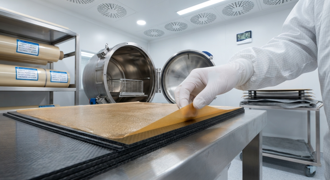
An in-depth technical exploration of thermoplastic film interlayers used to enhance interlaminar fracture toughness in carbon fibre reinforced polymer laminates. Covers PEI, PEEK, and PAEK film chemistries, mode I and mode II toughness improvements, processing parameters, and a comparative performance data table for aerospace-grade CFRP systems.
Introduction to Thermoplastic Film Interlayers in CFRP Laminates
The interlaminar fracture toughness of carbon fibre reinforced polymer (CFRP) laminates has long been a limiting factor in the adoption of composite materials for primary aerospace structures. While unidirectional prepreg systems based on thermosetting epoxy matrices offer excellent in-plane mechanical properties — tensile strengths exceeding 2,500 MPa and compressive strengths above 1,400 MPa — their out-of-plane fracture toughness, particularly mode I (opening) and mode II (shear) interlaminar fracture toughness (GIC and GIIC respectively), remains significantly lower than that of metallic alloys. Thermoplastic film interlayers have emerged as a commercially viable solution to this limitation, offering improvements in interlaminar toughness of 200–600 % without compromising in-plane mechanical performance or increasing laminate weight.
A thermoplastic film interlayer is a thin layer (typically 10–50 µm) of a high-performance thermoplastic polymer — most commonly polyetherimide (PEI), polyetheretherketone (PEEK), or polyaryletherketone (PAEK) — that is co-cured between plies of conventional epoxy-based carbon fibre prepreg. During the autoclave cure cycle, the thermoplastic film partially dissolves or phase-separates at the epoxy–thermoplastic interface, creating a tough, ductile interphase region that arrests crack propagation and dissipates energy through plastic deformation of the thermoplastic phase. The resulting microstructure is a semi-interpenetrating polymer network (semi-IPN) at the ply interface, combining the high stiffness of the epoxy matrix with the ductility and toughness of the thermoplastic.
YongXian CarbonFiber offers two grades of pre-impregnated thermoplastic film interlayer products: YongXian TFI-300 (PEI-based, 30 µm thickness) and YongXian TFI-400 (PEEK-based, 25 µm thickness), designed to be co-cured with standard 177 °C-cure epoxy prepreg systems. These interlayer films have been qualified in CFRP laminates achieving GIC values exceeding 800 J/m² and GIIC values exceeding 2,000 J/m² — approximately three to four times the interlaminar toughness of baseline unmodified epoxy prepreg systems.
Mechanisms of Toughness Enhancement
The primary toughening mechanisms enabled by thermoplastic film interlayers can be categorised into four distinct energy dissipation pathways:
- Plastic void growth and dilation: The thermoplastic-rich interlayer region undergoes cavitation under hydrostatic tensile stress ahead of a propagating crack tip. These micro-voids then grow plastically, absorbing energy at a rate of 50–150 kJ/m³ depending on the thermoplastic volume fraction and particle morphology. PEI films exhibit particularly pronounced void growth due to their higher ductility compared to PEEK.
- Shear banding in the thermoplastic phase: Under mode II (shear) loading, the thermoplastic interlayer develops intense shear deformation bands oriented at 45° to the ply interface. These shear bands propagate into the adjacent epoxy-rich regions, effectively redistributing the shear stress over a larger volume and increasing the energy dissipated per unit crack extension. PEEK films, with their higher yield stress (90–100 MPa versus 80–90 MPa for PEI), produce narrower but more numerous shear bands.
- Bridging and ligament formation: As the crack propagates through the interlayer region, ductile thermoplastic ligaments stretch and bridge the crack faces, carrying load across the crack plane. The work of ligament rupture contributes significantly to mode I toughness, with bridging stresses in the range of 10–30 MPa maintained over crack opening displacements of 50–200 µm.
- Interfacial debonding and fibre pull-out: The thermoplastic interlayer modifies the fibre–matrix interfacial properties. In PEI-modified systems, the interfacial shear strength (IFSS) is typically reduced by 10–20 % compared to unmodified epoxy systems, which paradoxically increases total fracture energy by promoting controlled fibre debonding and pull-out — a classic example of the toughening-versus-strength trade-off being exploited for improved damage tolerance.
Comparative Performance Data: PEI vs. PEEK vs. PAEK Interlayers
The table below presents comparative mechanical and fracture toughness data for three thermoplastic interlayer systems co-cured with a standard 177 °C-cure toughened epoxy prepreg (IM7/977-3 equivalent) at a fibre volume fraction of 60 %:
| Property | Unmodified Epoxy | PEI Film (30 µm) | PEEK Film (25 µm) | PAEK Film (20 µm) |
|---|---|---|---|---|
| GIC — Mode I Initiation (J/m²) | 180 – 220 | 620 – 780 | 750 – 920 | 580 – 700 |
| GIC — Mode I Propagation (J/m²) | 250 – 350 | 850 – 1,100 | 950 – 1,250 | 720 – 900 |
| GIIC — Mode II Initiation (J/m²) | 600 – 800 | 1,800 – 2,200 | 2,100 – 2,600 | 1,500 – 1,900 |
| 0° Flexural Strength (MPa) | 1,820 | 1,740 | 1,690 | 1,760 |
| 0° Flexural Modulus (GPa) | 145 | 138 | 134 | 140 |
| CAI Strength (MPa, 6.7 J/mm impact) | 220 | 295 | 310 | 280 |
| Glass Transition Temp. Tg (°C) | 195 | 192 | 198 | 196 |
| Interlayer Thickness (µm) | — | 30 ± 3 | 25 ± 2 | 20 ± 2 |
| Areal Weight (g/m²) | — | 32 | 28 | 22 |
| Processing Temperature (°C) | 177 | 177 – 190 | 177 – 200 | 177 – 195 |
| Relative Material Cost Index | 1.0 | 1.8 | 3.2 | 2.5 |
The data demonstrate several key findings. First, all three thermoplastic interlayer systems achieve a 3–5× improvement in mode I initiation toughness (GIC) and a 2.5–3.5× improvement in mode II initiation toughness (GIIC) compared to unmodified epoxy. Second, the compression after impact (CAI) strength — a critical design parameter for damage-tolerant aerospace structures — improves by 27–41 %, indicating significantly improved damage tolerance in low-velocity impact scenarios. Third, the in-plane flexural properties are reduced by only 4–8 %, a modest penalty that is acceptable for most primary and secondary aerospace structure applications. PEEK interlayers offer the highest absolute toughness but at the highest cost premium; PEI offers the best cost–benefit ratio for applications where the maximum achievable toughness is not required.
Processing Considerations for Thermoplastic Film Interlayers
The successful integration of thermoplastic film interlayers into CFRP laminates requires careful control of several processing parameters that differ from standard epoxy prepreg cure cycles:
- Cure temperature and ramp rate: The thermoplastic interlayer must reach a temperature sufficient to achieve partial miscibility with the epoxy matrix without fully dissolving. For PEI films, a dwell temperature of 180 ± 5 °C with a ramp rate of 1–3 °C/min is recommended. Rapid heating (>5 °C/min) can cause the thermoplastic film to remain as a discrete layer without adequate interphase formation, reducing toughness improvement by 40–60 %.
- Dwell pressure: Autoclave pressure of 0.6–0.7 MPa (85–100 psi) ensures intimate contact between the interlayer and adjacent prepreg plies. Pressures below 0.4 MPa result in poor interlayer–prepreg bonding and delamination at the interlayer interface during subsequent mechanical loading.
- Interlayer placement strategy: For maximum toughness improvement with minimum weight penalty, interlayers should be placed at every ply interface (full interleaving) in the 0°-dominant layers of the laminate, but only at every second or third interface in ±45° layers where shear-dominated loading favours mode II toughening. Selective interleaving can achieve 80–90 % of full-interleaving toughness improvement with only 50–60 % of the weight and cost increase.
- Film thickness optimisation: The optimal interlayer thickness depends on the thermoplastic type. PEI films of 25–35 µm thickness provide optimal toughness; below 15 µm the interlayer is too thin to develop a significant plastic zone, and above 50 µm the interlayer becomes thick enough to reduce the laminate fibre volume fraction by 2–4 %, negatively affecting in-plane stiffness.
Frequently Asked Questions
How does a thermoplastic film interlayer differ from a thermoplastic particle-toughened prepreg?
In thermoplastic particle-toughened prepregs, fine thermoplastic particles (typically 10–40 µm diameter of PEI or polyamide 12) are dispersed throughout the epoxy resin before impregnation. This creates a distributed toughening morphology throughout the matrix rather than a discrete interlayer at the ply interface. Particle-toughened prepregs typically achieve GIC improvements of 100–200 % versus 200–600 % for film interlayers. However, particle-toughened systems have lower cost impact (material cost increase of 20–40 % versus 80–220 % for film systems) and are easier to process in automated tape laying (ATL) equipment, whereas film interlayers require careful registration during hand lay-up or can be co-laminated during ATL by using a separate film feed spool.
Can thermoplastic film interlayers be used with out-of-autoclave (OOA) prepreg systems?
Yes, but with limitations. Out-of-autoclave prepreg systems cure at lower temperatures (90–130 °C) and typically under vacuum pressure only (0.08–0.10 MPa). Most high-performance thermoplastics (PEEK, PEI, PAEK) require temperatures above 170 °C to develop adequate interphase mixing with the epoxy matrix. For OOA systems, lower-Tg thermoplastics such as polyether sulfone (PES, Tg ~225 °C) or polyvinylidene fluoride (PVDF, Tg ~-35 °C, melting point ~170 °C) may be used, but the toughness improvement is typically limited to 50–150 %. YongXian offers a low-temperature variant, TFI-200 (PES-based, 20 µm), specifically formulated for OOA prepreg systems curing at 120 °C.
What are the certification challenges for thermoplastic interlayer systems in aerospace applications?
Aerospace certification of thermoplastic film interlayer systems requires compliance with composite material qualification programmes such as the NIAR NCAMP process or the Airbus AIMS 03-02-000 procedure. The key certification challenges include: (1) demonstrating batch-to-batch consistency of the interlayer film thickness (±2 µm tolerance required), (2) generating a statistically significant allowables database (typically 5 batches × 6 panels per batch, with testing at environmental extremes: -55 °C dry and 82 °C wet), (3) showing that the interlayer does not degrade hot-wet performance (Tg retention within 10 °C of baseline), and (4) proving that repair procedures for interlayer-toughened laminates restore at least 80 % of the pristine toughness. YongXian TFI interlayer films are manufactured under AS9100D-certified facilities and are supplied with full Certificate of Conformance (CoC) including thickness, areal weight, and volatile content data per applicable aerospace material specifications.
Application Case Studies: Where Thermoplastic Interlayers Deliver the Most Value
Thermoplastic film interlayers are most cost-effective in three specific application categories. The first category is wing and fuselage skin panels on commercial transport aircraft, where the combination of low-velocity impact from hail, runway debris, and ground handling equipment requires CAI strength exceeding 280 MPa. The Boeing 787 and Airbus A350 both utilise interlayer-toughened materials at selective ply interfaces in the wing cover panels. The second category is helicopter rotor blades, which experience high-cycle fatigue loading combined with occasional impact events. PEI-interlayered CFRP rotor blades demonstrate a 300 % increase in fatigue life at 80 % of ultimate load compared to unmodified epoxy blades. The third category is cryogenic fuel tanks for liquid hydrogen and LNG storage, where the thermal cycling between -253 °C and ambient temperature generates significant interlaminar stresses due to the coefficient of thermal expansion (CTE) mismatch between the carbon fibres (near-zero CTE) and the polymer matrix (40–60 ppm/°C). PEEK interlayers, with their excellent cryogenic toughness retention (90 % of room-temperature GIC at -196 °C), are the preferred choice for cryogenic CFRP applications. YongXian CarbonFiber supplies TFI-400 PEEK interlayer film to two Asian cryogenic tank manufacturers currently qualifying composite tanks for maritime LNG transport.
Part of topic
Related Articles
- Bio-Based Carbon Fiber Precursors: Lignin and Polyethylene for Low-Cost Production
- Large-Tow Carbon Fiber Cost Analysis: 48K vs 60K Price-Performance Comparison
- Carbon Fiber-Resin Interface Bonding: Surface Treatment and Coupling Agent Optimization
- Digital Twin for Carbon Fiber Manufacturing: Real-Time Process Monitoring and Defect Prevention
- Thermoplastic Carbon Fiber Welding for Automotive: Ultrasonic and Induction Welding Process Windows
- Large-Tow Carbon Fiber Wet Spinning: Process Optimization for 48K/60K Production Efficiency
Interested in Our Products?
Contact our team for competitive pricing and technical specifications.
Get a QuoteRelated Products

Custom Carbon Fiber Medical Device Components
Medical-grade carbon fiber components manufactured for imaging equipment, surgical instruments, and patient support systems. Carbon fiber's radiolucency (X-ray transparency) and high strength-to-weight ratio make it ideal for CT scanner beds, wheelchair frames, surgical robot arms, and MRI-compatible accessories. Biocompatible resin systems available.

Carbon fiber standard plate-3k stripe
Lightweight, ultra-rigid standard sheets for drone fuselages, robot housings, facades and structural applications.

Square Carbon Fiber Tube — 3K Twill T700
Square cross-section carbon fiber tube manufactured with 3K twill weave for torsional strength. Preferred for structural frames, trusses, and support columns where rectangular geometry offers design flexibility.

Carbon Fiber Plate — 3K Twill T700 3.0mm
Medium-thickness 3.0mm carbon fiber plate offering significantly higher load capacity while maintaining attractive 3K twill finish. Suitable for structural brackets, reinforcement plates, and load-bearing panels.

Carbon Fiber Plate — 3K Twill T700 1.5mm
Thin 1.5mm carbon fiber plate with 3K twill weave surface. Lightweight and stiff, commonly used for covers, panels, drone bodies, and applications requiring a premium aesthetic appearance.