
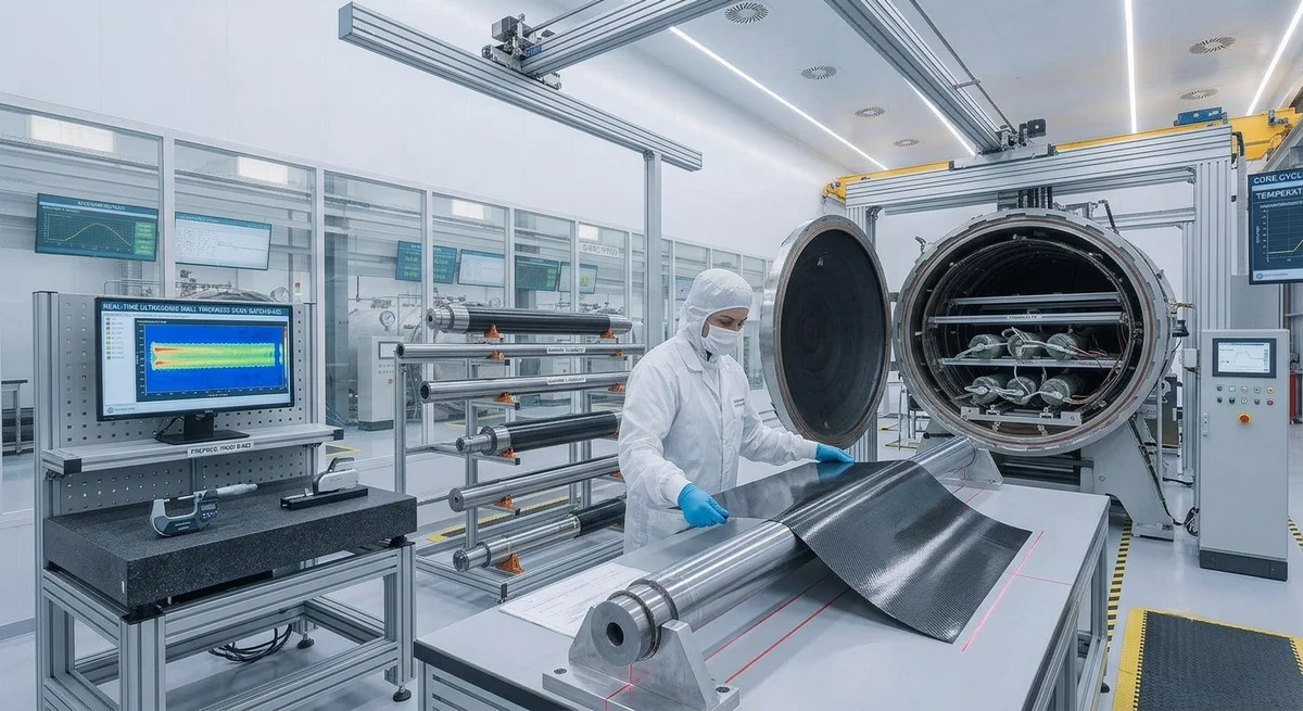
Roll-wrapped carbon fiber tube manufacturing is a critical production method for high-performance tubular components used across aerospace, sporting goods, industrial automation, a
The Manufacturing Process in Detail
Step 1: Material Preparation
The process begins with selecting the appropriate prepreg material. Standard roll-wrapped tube production uses unidirectional (UD) or woven carbon fiber prepreg with epoxy resin systems. Common material specifications include:
- UD prepreg: T700SC 12K (standard modulus, 240 GPa) for general structural applications
- Woven prepreg: 3K plain weave or 2x2 twill for improved torsional strength and surface aesthetics
- High-modulus prepreg: M40J or M55J fibers for stiffness-critical applications in aerospace
Prepreg is stored at -18°C and thawed to room temperature in sealed bags for 8-12 hours before use, preventing moisture condensation on the material surface — a critical quality step often overlooked.
Step 2: Mandrel Selection and Preparation
Mandrels are typically precision-ground steel or aluminum rods with surface hardness of 60+ HRC (for steel) to prevent scoring during repeated use. Key mandrel specifications:
| Parameter | Typical Range | Impact on Quality |
|---|---|---|
| Diameter tolerance | ±0.02 mm | Determines final tube ID precision |
| Surface finish | Ra 0.4 µm or better | Affects internal surface quality and release |
| Taper per meter | <0.05 mm/m | Ensures uniform wall thickness |
| Hardness (steel) | 60-65 HRC | Dimensional stability over production cycles |
Step 3: Ply Cutting and Layup
Prepreg plies are cut to precise widths using CNC cutting tables or ultrasonic knife systems. The ply width determines the final tube length, while the number of plies determines wall thickness. A typical layup sequence for a 25 mm diameter structural tube might include:
1. Inner ply: ±45° woven fabric for torsional rigidity (0.2 mm cured thickness)
2. Middle plies: 0° UD plies for axial strength (0.125 mm per ply, 4 plies = 0.5 mm)
3. Outer ply: ±45° woven fabric for impact resistance and surface finish
4. Optional: Surface veil for enhanced UV resistance and paint adhesion
Total cured wall thickness: approximately 0.9-1.0 mm
Step 3: Roll Wrapping
The cut prepreg plies are sequentially wrapped around the mandrel on a rolling table. Tension control during wrapping is critical — insufficient tension causes wrinkles and voids, while excessive tension can distort fiber orientation. Modern wrapping machines apply programmable tension from 2-15 N per ply layer, adjustable in 0.5 N increments.
Step 4: Curing
Wrapped tubes are vacuum-bagged and cured in an autoclave or oven. Standard cure cycles for 120°C-cure epoxy prepreg:
| Phase | Temperature | Time | Pressure | Purpose |
|---|---|---|---|---|
| Ramp 1 | 25°C → 80°C | 30 min | Atmospheric | Resin flow initiation |
| Dwell 1 | 80°C | 30 min | 0.5 bar vacuum | Resin stabilization, volatile removal |
| Ramp 2 | 80°C → 120°C | 45 min | 3-5 bar (autoclave) | Full cure temperature ramp |
| Dwell 2 | 120°C | 90 min | 3-5 bar (autoclave) | Complete polymerization |
| Cool-down | 120°C → 40°C | 60 min | Gradual release | Thermal stress prevention |
Step 5: Demolding and Post-Cure Processing
After cooling, tubes are extracted from mandrels using hydraulic or pneumatic pullers. Tubes then undergo:
- Visual inspection: Surface defects, porosity, fiber exposure
- Dimensional inspection: OD, ID, wall thickness (ultrasonic measurement)
- Mechanical testing: Flexural modulus, ultimate strength (sample batch testing)
- Cut-to-length: Diamond-tipped cutting for precision (±0.5 mm tolerance)
Optional post-processing includes sanding, painting, or CNC machining of end fittings.
Common Defects and Prevention
Fiber Wrinkling
Caused by uneven tension during wrapping or mismatched ply angles. Prevention: maintain tension within ±1 N of target and use tapered shims for transition areas.
Porosity/Voids
Result of entrapped air between plies or incomplete resin flow. Prevention: apply vacuum bag with 0.8 bar minimum vacuum level and use a 30-minute debulk cycle at 50°C before final cure ramp.
Wall Thickness Variation
Typically caused by mandrel wear, uneven prepreg thickness, or inconsistent wrapping tension. Prevention: replace mandrels after 500 cycles, use prepreg with ±0.02 mm thickness tolerance, and implement real-time tension monitoring.
Cost Considerations for B2B Buyers
Roll-wrapped tube pricing depends on several factors:
| Cost Factor | Impact | Notes |
|---|---|---|
| Material grade | T700 vs M55J can differ 4-6x | Standard modulus for non-aerospace |
| Wall thickness | +15-20% per additional mm | Thicker = more plies + longer cure |
| Diameter | +10-25% for non-standard sizes | Custom mandrel cost amortization |
| Surface finish | +5-15% for paint-ready | Additional sanding + primer cost |
| Volume (annual) | -10-30% for 1,000+ units | Tooling amortization + material negotiation |
FAQ
What is the difference between roll-wrapped and filament-wound carbon fiber tubes?
Roll wrapping provides better dimensional accuracy and surface finish for tubes with length-to-diameter ratios under 50:1, while filament winding excels at high-length, high-pressure applications such as drive shafts and pressure vessels. Roll wrapping also allows easier incorporation of ±45° plies for torsional performance.
What is the typical lead time for custom roll-wrapped tubes?
Standard lead times range from 4-6 weeks for first articles, including tooling preparation (mandrel procurement or manufacture) and process validation. Repeat orders typically reduce to 2-3 weeks. Rush orders with existing tooling can be completed in 5-7 business days.
How do I specify carbon fiber tube quality requirements to a supplier?
Provide a detailed specification including: tube OD/ID tolerances, wall thickness, fiber orientation per ply, required flexural modulus and strength, surface finish requirements, and applicable test standards (ISO 13003 for fatigue, ASTM D790 for flexural properties). Request material certification and process documentation as part of your quality agreement.
Part of topic
Related Articles
- Bio-Based Carbon Fiber Precursors: Lignin and Polyethylene for Low-Cost Production
- Large-Tow Carbon Fiber Cost Analysis: 48K vs 60K Price-Performance Comparison
- Carbon Fiber-Resin Interface Bonding: Surface Treatment and Coupling Agent Optimization
- Digital Twin for Carbon Fiber Manufacturing: Real-Time Process Monitoring and Defect Prevention
- Thermoplastic Carbon Fiber Welding for Automotive: Ultrasonic and Induction Welding Process Windows
- Large-Tow Carbon Fiber Wet Spinning: Process Optimization for 48K/60K Production Efficiency
Interested in Our Products?
Contact our team for competitive pricing and technical specifications.
Get a QuoteRelated Products

Carbon fiber standard plate-3k stripe
Lightweight, ultra-rigid standard sheets for drone fuselages, robot housings, facades and structural applications.

Carbon Fiber Plate — 3K Twill T700 1.5mm
Thin 1.5mm carbon fiber plate with 3K twill weave surface. Lightweight and stiff, commonly used for covers, panels, drone bodies, and applications requiring a premium aesthetic appearance.

Square Carbon Fiber Tube — 3K Twill T700
Square cross-section carbon fiber tube manufactured with 3K twill weave for torsional strength. Preferred for structural frames, trusses, and support columns where rectangular geometry offers design flexibility.

Carbon Fiber Plate — 3K Twill T700 3.0mm
Medium-thickness 3.0mm carbon fiber plate offering significantly higher load capacity while maintaining attractive 3K twill finish. Suitable for structural brackets, reinforcement plates, and load-bearing panels.

Carbon Fiber Plate — UD Unidirectional T700
Unidirectional carbon fiber plate with all fibers oriented in a single direction for maximum strength along the fiber axis. Essential for structural reinforcements, splints, and applications where load direction is predictable.