
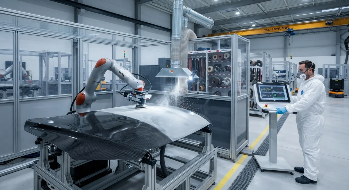
A comprehensive B2B analysis of robotic sanding and finishing systems for carbon fiber composite parts, covering abrasive selection, force-controlled end effectors, process parameters for surface preparation, dust extraction, and quality assurance for aerospace and automotive production.
Introduction
The global carbon fiber reinforced polymer (CFRP) market is projected to reach $8.9 billion by 2028, with automotive, aerospace, and wind energy sectors driving demand for high-volume, high-quality composite components. However, one of the most persistent bottlenecks in CFRP production remains the finishing stage — the sanding, grinding, and surface preparation operations that are required after demolding to achieve the dimensional tolerances, surface finish specifications, and adhesive bonding surface quality demanded by OEM customers. Unlike metals, which have well-established automated grinding and polishing processes, carbon fiber composites present unique challenges for automated finishing: the material's anisotropic structure, abrasive sensitivity to fiber damage, conductive dust hazards, and the need to avoid delamination at ply edges make manual sanding the default approach in most composite manufacturing facilities.
Manual sanding of carbon fiber parts is labor-intensive, inconsistent, and increasingly unsustainable at production scales exceeding 10,000 parts per year. A typical aerospace-grade CFRP component requires 15–45 minutes of manual sanding per square meter, with surface finish quality varying significantly between operators and shifts. The automotive industry's push toward structural carbon fiber components — with Class A surface finish requirements of Ra ≤ 0.8 µm for visible exterior panels — has made automated finishing systems a strategic necessity for Tier 1 composite suppliers. Robotic sanding cells equipped with force-controlled end effectors, real-time process monitoring, and intelligent abrasive wear compensation are now being deployed by leading composite manufacturers to achieve consistent surface quality, reduce cycle times by 50–70%, and eliminate operator exposure to respirable carbon fiber dust.
This article provides a comprehensive technical analysis of robotic sanding and finishing systems for carbon fiber composite parts, covering abrasive material selection, force-controlled end effector technology, process parameter optimization, dust extraction and safety systems, inline quality assurance methods, and implementation best practices for B2B buyers evaluating automation investments for their composite finishing operations.
Abrasive Selection for Carbon Fiber Composite Sanding
The selection of abrasive media is the most critical process parameter in robotic sanding of carbon fiber composites. Unlike metal grinding — where the abrasive removes material primarily through chip formation — sanding of CFRP involves abrasive grains simultaneously cutting through three distinct material phases: the brittle carbon fibers (7–10 µm diameter for standard 3K tow), the ductile epoxy matrix, and the fiber-matrix interphase region. This multi-phase cutting action imposes conflicting requirements on the abrasive system: the grains must be sharp enough to cleanly sever carbon fibers without pulling them out of the matrix, yet the bond between grains must be precisely engineered to release worn grains before the accumulated friction heat exceeds the epoxy glass transition temperature (typically 120–180°C for standard epoxy systems).
For robotic CFRP sanding applications, aluminum oxide (Al₂O₃) abrasive belts and discs are the most widely used media, offering a good balance of cutting efficiency and thermal stability. The optimal grit size depends on the process stage: rough sanding (grit 80–120) for flash removal and thickness adjustment removes 0.1–0.3 mm per pass at belt speeds of 15–25 m/s; intermediate sanding (grit 180–240) for surface leveling and defect removal removes 0.05–0.15 mm per pass; fine sanding (grit 320–400) achieves the surface finish required for paint adhesion (Ra 0.8–1.6 µm); and ultra-fine sanding (grit 600–800) produces the Class A surface finish (Ra ≤ 0.4 µm) required for visible exterior automotive panels. Silicon carbide (SiC) abrasives offer 20–30% higher initial cutting efficiency on CFRP than aluminum oxide due to their sharper grain geometry, but they wear 40–60% faster and generate higher surface temperatures, increasing the risk of matrix smearing and thermal degradation at the surface layer. For robotic applications where consistent material removal over long production runs is critical, aluminum oxide with a stearate anti-loading coating is the recommended abrasive medium.
An emerging technology in CFRP abrasive finishing is the use of diamond-impregnated abrasive pads for the final polishing stage. Electroplated diamond discs with 10–30 µm diamond grit embedded in a nickel bond matrix achieve consistent surface finishes of Ra 0.2–0.4 µm with minimal abrasive wear over 500–2,000 parts per disc — compared to 50–200 parts per disc for conventional aluminum oxide belts at the same grit size. The high thermal conductivity of diamond (2,200 W/m·K) pulls heat away from the sanding interface, reducing the surface temperature of the CFRP part by 15–25°C compared to aluminum oxide at identical process parameters. The capital cost premium for diamond abrasive tooling is significant — typically $80–$200 per disc versus $5–$15 for aluminum oxide — but the extended tool life and superior surface finish consistency make diamond finishing economical for high-volume production runs exceeding 5,000 parts per year.
Force-Controlled Robotic End Effectors for CFRP Sanding
The fundamental challenge in robotic sanding of carbon fiber composites is maintaining consistent contact pressure between the abrasive medium and the contoured part surface. Carbon fiber parts — particularly those produced by compression molding or resin transfer molding (RTM) — exhibit dimensional variations of ±0.3–0.8 mm across the part surface due to thermal shrinkage anisotropy, mold wear, and fiber volume fraction gradients. A rigid robotic arm programmed to follow a nominal CAD surface path will apply varying contact forces as the part geometry deviates from the nominal surface, resulting in inconsistent material removal, localized overheating, and potential fiber damage at pressure peaks.
Force-controlled end effectors solve this problem by actively regulating the normal force applied to the abrasive contact surface, independent of the robot's position within a compliance window. Three force control technologies are commercially available for CFRP sanding applications. Pneumatic force control — using a double-acting air cylinder with a proportional pressure regulator and load cell feedback — offers a force range of 10–150 N with a bandwidth of 5–15 Hz and positioning compliance of ±3–5 mm. Pneumatic systems are the most common choice for automotive CFRP finishing due to their low cost ($4,000–$12,000 per end effector) and robustness to dust contamination. Electric servo force control — using a linear servo motor with encoder and force sensor feedback — achieves a force range of 5–200 N with a bandwidth of 20–50 Hz and positioning compliance of ±8–12 mm. Servo systems are preferred for aerospace applications where force accuracy of ±0.5 N and real-time force profile logging are required for process qualification. Compliant constant-force spring mechanisms — using pre-loaded spring cartridges with adjustable preload — provide the simplest and most robust solution, with a fixed force setting of 20–80 N and ±2 mm compliance, suitable for rough sanding operations where force precision is less critical.
The following table compares the three force control technologies used in robotic CFRP sanding across key performance parameters for B2B buyers evaluating system specifications.
| Parameter | Pneumatic | Electric Servo | Compliant Spring |
|---|---|---|---|
| Force range (N) | 10–150 | 5–200 | 20–80 |
| Force accuracy (±N) | 2.0–3.0 | 0.3–0.5 | 5.0–8.0 |
| Control bandwidth (Hz) | 5–15 | 20–50 | N/A (passive) |
| Compliance range (mm) | ±3–5 | ±8–12 | ±2 |
| Force profile logging | Optional | Standard | Not possible |
| Dust resistance | Good (class IP54) | Moderate (IP42) | Excellent (IP65) |
| System cost (USD) | $4,000–$12,000 | $15,000–$35,000 | $1,500–$4,000 |
| Typical application | Automotive, general industrial | Aerospace, high-precision | Rough sanding, flash removal |
| Maintenance interval | 500–1,000 hours | 2,000–5,000 hours | 1,000–2,000 hours |
Process Parameters and Surface Quality Optimization
Robotic sanding of CFRP involves five interdependent process parameters that must be optimized for each part geometry and surface finish specification. Contact force (Fₙ): For fine and ultra-fine sanding of carbon fiber composites, the optimal contact force is 25–45 N. Below 15 N, the abrasive grains skid across the surface without effective cutting, generating frictional heat without material removal. Above 60 N, the abrasive grains penetrate below the surface fiber layer, causing fiber pullout and increasing surface roughness (Ra increases by 40–80% at 80 N compared to 35 N for the same grit size). Force-controlled end effectors should maintain the contact force within ±3 N of the set point during the sanding pass.
Feed rate (v_f): The robot tool center point (TCP) feed rate for CFRP sanding ranges from 50 mm/s for fine finishing to 500 mm/s for rough material removal. The optimal feed rate is inversely proportional to the contact force: at 35 N contact force, a feed rate of 150 mm/s achieves the highest material removal rate (0.08–0.12 mm per pass) while maintaining Ra below 0.8 µm with grit 400 abrasive. Feed rates above 300 mm/s at the same force cause incomplete fiber cutting and increased surface fuzziness. Abrasive belt speed (v_s): For robotic CFRP sanding, the optimal belt speed range is 12–20 m/s for aluminum oxide abrasives. Below 10 m/s, the abrasive action transitions from cutting to plowing, generating excessive heat and matrix smearing. Above 25 m/s, the surface temperature can exceed the epoxy Tg in the surface layer (1–3 µm depth), causing resin degradation and reduced paint adhesion strength. Path overlap ratio: Successive sanding passes should overlap by 30–50% of the abrasive contact width to eliminate visible witness marks and achieve uniform surface finish across the entire part area. A 40% overlap ratio is the standard recommendation, balancing finishing time against surface uniformity.
Abrasive wear compensation: As the abrasive belt or disc wears during production, the material removal rate decreases and the surface finish characteristics change. Robotic sanding cells should incorporate in-process abrasive wear monitoring using either (a) spindle motor current monitoring — a 15–25% increase in motor current relative to the baseline for a new belt indicates sufficient wear to trigger a belt index or replacement — or (b) optical surface roughness measurement after each part using a chromatic confocal sensor, with abrasive replacement triggered when the measured Ra exceeds the specification limit by a 20% safety margin. Automated abrasive belt indexing systems, which advance the belt by 50–100 mm after each part, maintain consistent cutting performance across the entire belt width and extend effective belt life by 300–500% compared to fixed-position operation.
Dust Extraction and Safety for Carbon Fiber Sanding
Robotic sanding of carbon fiber composites generates respirable dust particles that present both occupational health hazards and facility contamination risks. Carbon fiber dust particles in the respirable size range (< 10 µm aerodynamic diameter) can cause mechanical irritation of the upper respiratory tract, and some PAN-based carbon fiber grades have been classified as potential irritants under extended exposure scenarios. Additionally, carbon fiber dust is electrically conductive — the bulk resistivity of dry carbon fiber dust is 0.1–1.0 Ω·cm — creating a risk of short-circuiting unprotected electrical equipment and, under specific conditions, static discharge ignition in environments where combustible dust or solvent vapors are present.
Robotic CFRP sanding cells must incorporate a multi-stage dust management system. The primary dust extraction system should achieve a capture velocity of at least 0.5 m/s at the sanding interface, drawing air through a 100–150 mm diameter extraction hood positioned within 50 mm of the abrasive contact point. Total airflow of 800–1,500 m³/hour per sanding spindle is required, with the exhaust directed to a HEPA-filtered dust collection unit rated for conductive dust (grounded filter cartridges with stainless steel construction to prevent static accumulation). The secondary filtration stage should use a HEPA H13 or H14 filter with a minimum efficiency of 99.95% at 0.3 µm MPPS (Most Penetrating Particle Size) to ensure that respirable carbon fiber fragments are captured before air recirculation. For facilities processing more than 500 kg of CFRP material per month, the dust extraction system should be monitored by a continuous particulate monitor with alarms triggered at 50% of the occupational exposure limit (typically 1 mg/m³ for respirable dust under ACGIH TLVs).
Workers involved in robotic CFRP sanding operations — including robot programmers, maintenance technicians, and quality inspectors — should wear Type 5 (particulate-protective) disposable coveralls and P3-rated half-mask respirators when entering the sanding cell for programming, part loading/unloading, or maintenance activities. The sanding cell should be maintained under negative pressure relative to the surrounding production area, with a minimum of 6–12 air changes per hour and pressure differential of 5–15 Pa. Explosion-proof electrical classification (Zone 22 per IEC 60079 or Class II Division 2 per NEC) should be specified for all electrical equipment within 2 m of the sanding zone where combustible carbon fiber dust may accumulate on horizontal surfaces.
Inline Quality Assurance and Process Monitoring
- In-process surface roughness measurement: Chromatic confocal or laser triangulation sensors mounted on the robot end effector, offset 100–200 mm from the sanding contact point, measure the surface Ra in real time. The sensor data is compared to the specification limit (e.g., Ra ≤ 0.8 µm for paint-ready surfaces) and the robot adjusts the sanding pass count, feed rate, or contact force in a closed loop to achieve the target finish. This closed-loop control reduces the reject rate from 5–8% in manual sanding to less than 0.5% in automated sanding with inline metrology.
- Automated visual inspection for surface defects: A machine vision system — using a 5–12 MP monochrome camera with coaxial LED lighting at a 30–45° incidence angle — captures images of the sanded surface and applies deep learning-based defect detection to identify surface pitting (minimum detectable size 0.3 mm), fiber breakout (0.5 mm), matrix smearing (1.0 mm), and incomplete sanding areas (2.0 mm). The defect classifier, trained on a minimum of 5,000 labeled images of CFRP surface defects, achieves a detection accuracy of 98.5–99.2% with a false positive rate below 2%.
- Thickness gauging integration: An ultrasonic thickness gauge (5–10 MHz contact or air-coupled transducer) measures the CFRP part thickness at 5–20 pre-defined locations after sanding to verify that the material removal has not reduced the structural laminate below the minimum design thickness. The thickness data is automatically logged to the part serial number and compared to the engineering drawing tolerances (typically ±0.15 mm from nominal). Parts with thickness readings below the minimum acceptable value are quarantined for engineering review, preventing the release of structurally compromised components.
- Surface energy measurement for bonding quality: For parts that will undergo secondary bonding — a common requirement for aerospace CFRP assemblies — the sanded surface must achieve a minimum surface energy of 45–50 mN/m to ensure adequate adhesive wetting and bond strength. Inline surface energy measurement using a contact angle goniometer (water contact angle ≤ 35°) or dyne test pen verification at critical locations provides real-time confirmation that the sanding process has adequately activated the surface without leaving release agent residues or over-polished zones.
Implementation and Return on Investment
The capital investment for a robotic CFRP sanding cell varies significantly based on part complexity, production volume, and quality requirements. A single-robot sanding cell (1 × 6-axis industrial robot, pneumatic force-controlled end effector, 200 mm belt sander, HEPA dust extraction, and cell enclosure) has a total installed cost of $180,000–$350,000. A dual-robot cell with electric servo force control, inline metrology, and vision-based defect detection costs $450,000–$750,000. The ROI analysis for a medium-volume composite manufacturer processing 20,000 CFRP parts per year shows: manual sanding labor cost at $18/part (25 minutes per part at $45/hour fully loaded labor rate); robotic sanding direct cost at $3.50/part (5 minutes cycle time, $40/hour robot depreciation + maintenance + energy); annual savings of $290,000; and a payback period of 14–22 months for a single-robot cell. Additional cost savings include reduction in consumable abrasive media (30–50% less due to optimized belt wear) and reduced reject/rework rate (from 6% manual to 0.5% robotic).
Frequently Asked Questions
Can robotic sanding handle complex 3D contoured carbon fiber parts?
Yes, modern robotic sanding systems are fully capable of finishing complex 3D contoured CFRP parts. The key enabling technology is the force-controlled end effector, which maintains consistent contact force across compound curves, concave pockets, and tight radii (down to 5 mm). For parts with undercuts or deep cavities, the robot can be programmed with a multi-axis tool approach path, and if the part has inaccessible zones, a secondary end effector with a smaller contact wheel (25–50 mm diameter) or a pencil-grinder tool can be automatically exchanged via a tool changer. The programming takes 40–120 hours for a complex part in offline simulation software (RoboDK, KUKA.Sim, or FANUC RoboGuide), including path planning, collision avoidance verification, and force control parameter optimization. Once programmed and validated, the same part program can be replicated across multiple production lines without programming variation.
What is the surface finish quality achievable with robotic CFRP sanding?
With optimized process parameters and appropriate abrasive selection, robotic sanding of carbon fiber composites can achieve surface finishes ranging from Ra 0.8–1.6 µm (grit 320, paint-ready) to Ra 0.2–0.4 µm (grit 800 with diamond polishing pad, Class A automotive exterior quality). The consistency across production runs is significantly better than manual sanding: the coefficient of variation (CV) for surface roughness across 100 consecutive parts is 8–12% for robotic sanding versus 25–40% for manual sanding by trained operators. For aerospace applications requiring surface preparation for adhesive bonding, robotic sanding with grit 180–240 achieves the optimal surface topography (Ra 1.5–3.0 µm with peaks at 5–15 µm spacing) that maximizes adhesive bond strength — achieving lap shear strengths of 28–35 MPa compared to 22–28 MPa for manually prepared surfaces in ASTM D5868 testing.
How does robotic sanding affect the structural integrity of carbon fiber parts?
Robotic sanding, when properly programmed with appropriate force control parameters, does not compromise the structural integrity of carbon fiber parts. The material removal is limited to 0.1–0.3 mm per pass (rough sanding) and 0.02–0.08 mm per pass (fine sanding), well within the typical surface ply thickness of 0.12–0.20 mm for 200 gsm 3K fabric. The risk of structural damage — including fiber breakage below the surface ply, delamination at ply edges, and thermal degradation of the epoxy matrix — is actually lower in robotic sanding than manual sanding because force control prevents the pressure spikes that occur when a manual operator encounters hard-to-reach areas or changes body position. Thermal imaging studies of robotic CFRP sanding show that the surface temperature during fine sanding (grit 400, Fₙ=35 N, v_f=150 mm/s) remains below 65°C — well within the safe thermal margin for standard epoxy systems (Tg ≥ 120°C). The resulting surface layer (2–5 µm depth) shows no evidence of matrix degradation or microcracking under SEM examination.
What are the main challenges in integrating robotic sanding into existing CFRP production lines?
The three main integration challenges are: (1) Part fixturing and dimensional variation — CFRP parts from different production batches may vary in geometry by ±0.5 mm or more due to process variation. The robotic sanding cell must include either a part measurement station (laser profile scanner or structured light sensor) that adjusts the robot path to each individual part, or a force-controlled end effector with sufficient compliance range to accommodate the expected variation. (2) Programming complexity for mixed-model production — facilities that produce multiple CFRP part variants on the same line face a programming overhead for each new part geometry. Offline programming with parametric templates can reduce this overhead to 8–20 hours per new variant if the parts share common feature families. (3) Dust management integration with existing HVAC systems — the HEPA-filtered dust extraction system for the sanding cell must be integrated with the facility's existing ventilation without creating pressure imbalances. A dedicated dust collection unit with a minimum 1,500 m³/hour capacity per cell, connected to the facility's exhaust stack, is the standard approach. Most Tier 1 composite manufacturers implementing robotic sanding report that the integration phase takes 4–8 weeks from delivery to full production acceptance.
Related Articles
- Bio-Based Carbon Fiber Precursors: Lignin and Polyethylene for Low-Cost Production
- Large-Tow Carbon Fiber Cost Analysis: 48K vs 60K Price-Performance Comparison
- Carbon Fiber-Resin Interface Bonding: Surface Treatment and Coupling Agent Optimization
- Digital Twin for Carbon Fiber Manufacturing: Real-Time Process Monitoring and Defect Prevention
- Thermoplastic Carbon Fiber Welding for Automotive: Ultrasonic and Induction Welding Process Windows
- Large-Tow Carbon Fiber Wet Spinning: Process Optimization for 48K/60K Production Efficiency
Interested in Our Products?
Contact our team for competitive pricing and technical specifications.
Get a QuoteRelated Products

Carbon fiber standard plate-3k stripe
Lightweight, ultra-rigid standard sheets for drone fuselages, robot housings, facades and structural applications.

Carbon Fiber Plate — 3K Twill T700 1.5mm
Thin 1.5mm carbon fiber plate with 3K twill weave surface. Lightweight and stiff, commonly used for covers, panels, drone bodies, and applications requiring a premium aesthetic appearance.

Square Carbon Fiber Tube — 3K Twill T700
Square cross-section carbon fiber tube manufactured with 3K twill weave for torsional strength. Preferred for structural frames, trusses, and support columns where rectangular geometry offers design flexibility.

Carbon Fiber Plate — 3K Twill T700 3.0mm
Medium-thickness 3.0mm carbon fiber plate offering significantly higher load capacity while maintaining attractive 3K twill finish. Suitable for structural brackets, reinforcement plates, and load-bearing panels.

Carbon Fiber Plate — UD Unidirectional T700
Unidirectional carbon fiber plate with all fibers oriented in a single direction for maximum strength along the fiber axis. Essential for structural reinforcements, splints, and applications where load direction is predictable.