
Carbon fiber aerospace parts rarely ship straight from the mold. Before primer and topcoat can go on, the surface needs a controlled profile: rough enough for the coating to key in mechanically, smooth enough that no fiber is exposed and no scratch valley traps air. For decades that pro
Introduction
Carbon fiber aerospace parts rarely ship straight from the mold. Before primer and topcoat can go on, the surface needs a controlled profile: rough enough for the coating to key in mechanically, smooth enough that no fiber is exposed and no scratch valley traps air. For decades that profile came from a human with a random orbital sander, and results varied with fatigue, grip pressure, and judgment.
That is changing. Force-controlled robotic sanding cells prepare carbon fiber surfaces with a repeatability manual finishing cannot approach. This article covers why manual sanding of carbon fiber reinforced polymer (CFRP) is inconsistent, how a robotic finishing cell is built, what Ra targets support paint adhesion, and how adhesion is validated before a part leaves the cell.
Why Manual Sanding of CFRP Is Inconsistent
Manual sanding fails for three compounding reasons. First, human force control is poor: applied pressure can vary by 30-50% between passes, creating oversanded zones with exposed fibers and undersanded resin-rich zones. Second, stroke pattern and dwell are unpredictable. Third, judgment changes over a shift; a tired operator presses harder.
The consequences are measurable:
- Inconsistent Ra means some zones fall outside the paint adhesion window, requiring re-sanding or causing adhesion failure in service.
- Oversanding breaks surface fibers, creating fuzz that traps dust and resists primer wet-out.
- Undersanded resin-rich zones give the primer a glossy, low-energy substrate with weak mechanical keying.
- Manual sanding spreads respirable carbon fiber dust onto fixtures and freshly prepared parts.
Because every operator produces a different result, manual finishing cannot deliver the statistical process control aerospace quality demands.
Robotic Sanding Cell Architecture
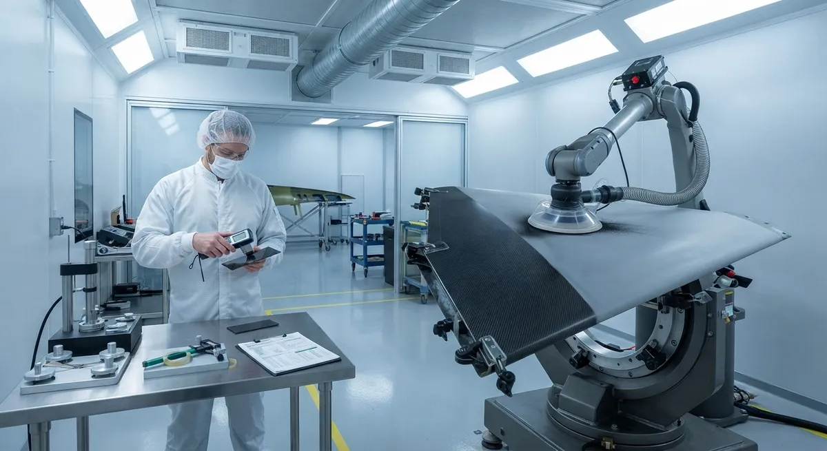
A robotic sanding cell combines four core elements: a six-axis robot, a force-controlled sanding tool, integrated vacuum extraction, and a part positioner. The robot carries a random orbital sander or belt head through a programmed path, while a force/torque sensor at the wrist measures normal force and adjusts the arm in real time. The tool does not fight the surface; it follows it at constant pressure.
Typical aerospace cell specifications:
- Six-axis robot with 1.8-3.2 m reach, covering the largest panel without refixturing.
- Force control resolution of ±1-3 N, with the sensor sampling at 100-500 Hz.
- Random orbital sander with 125-150 mm pad, or belt heads for long flat sections.
- On-tool HEPA vacuum extraction capturing 95-99% of dust at the source.
Enclosing the robot in a ventilated booth keeps carbon dust inside the cell.
Surface Profile Consistency and Paint Adhesion
The link between surface roughness and paint adhesion is the technical core of finishing. For aerospace epoxy primer systems on CFRP, the profile specified before priming is Ra 1.6-3.2 µm. Below Ra 1.6 µm the surface is too smooth for reliable mechanical keying; above Ra 3.2 µm, deep scratches trap air and leave starved coating that becomes an initiation site for delamination. The window is achievable by hand, but not holdable across a large part.
Robotic sanding holds the profile inside the window because pressure, feed rate, and grit are constant along the path. A typical sequence runs P180 for leveling, P320 for scratch refinement, and P400 for the paint-ready profile. The table below compares manual and robotic finishing on an aerospace panel:
| Parameter | Manual Sanding | Robotic Cell |
|---|---|---|
| Ra spread across a part (µm) | ±0.8 or more | ±0.1-0.2 |
| Target Ra before primer (µm) | 1.6-3.2, by feel | 1.6-3.2, measured per grid point |
| Cycle time, large wing skin | 45-60 minutes | 15-20 minutes |
| First-pass paint yield | 82-90% | 95-99% |
| Labor cost per part | Baseline | Reduced 50-70% |
| Pull-off adhesion after primer (ASTM D4541, MPa) | 3.5-7.0, scattered | 6.0-7.5, consistent |
| Process documentation | Operator log sheets | Automatic per-part digital record |
Uniform Ra means the primer sees the same substrate everywhere, so cure, gloss, and adhesion are uniform too.
Dust Removal and Contamination Control
Carbon fiber dust is conductive, abrasive, and a respiratory hazard when respirable. Manual sanding spreads it through the shop and onto freshly prepared parts, degrading the surface being finished. Robotic cells control dust at the source: on-tool extraction pulls the fine black dust from the sanding interface into HEPA-filtered collectors.
Between the final pass and primer application, parts are handled with dedicated gloves and covered transport, and some cells add an automatic dry-ice cleaning step before the primer booth.
Paint Adhesion Validation
Surface profile is only half the story; adhesion must be proven. Two standard methods dominate aerospace coating qualification. The pull-off test per ASTM D4541 bonds an aluminum dolly to the coated surface and pulls it perpendicularly until failure, reporting stress in MPa; aerospace primer on sanded CFRP typically accepts 3.5 MPa minimum and 5.0-7.0 MPa for production quality. The cross-cut test per ASTM D3359 scores a lattice of cuts and tapes them off, rating adhesion from 5B (no flaking) to 0B; acceptance is commonly 5B or 4B.
In an automated cell, validation is built into the workflow:
- Profile gauges measure Ra at grid points after the final grit, stored against the part serial number.
- Coupon parts from the same program are pull-off and cross-cut tested to verify the process.
- Force, feed rate, and tool wear data are logged per cycle for auditors.
This turns finishing into an auditable step with the data trail aerospace quality systems require.
Frequently Asked Questions
What Ra surface roughness is required for paint adhesion on carbon fiber?
Aerospace epoxy primer systems on sanded CFRP typically require Ra 1.6-3.2 µm before priming. Below that range the surface is too smooth for mechanical keying; above it, deep scratches trap air and create starved coating zones. Robotic sanding holds this window consistently, while manual finishing commonly varies by ±0.8 µm.
How much faster is robotic sanding than manual sanding?
On a large wing skin, a robotic cell completes the full grit sequence in 15-20 minutes versus 45-60 manually, a 60-70% cycle time reduction. Labor cost drops 50-70%, first-pass paint yield rises from 82-90% to 95-99%, and the cell can run unattended overnight.
What is the standard grit sequence for sanding carbon fiber before paint?
A common sequence is P180 for initial leveling, P320 for scratch refinement, and P400 for the paint-ready profile. The sequence depends on the coating system and surface condition, and is verified by profile measurement after the final grit.
Which adhesion tests are used for aerospace coatings on carbon fiber?
The two dominant methods are the pull-off test per ASTM D4541 and the cross-cut test per ASTM D3359. Pull-off values for aerospace primer on sanded CFRP typically run 3.5 MPa minimum to 5.0-7.0 MPa. Cross-cut acceptance is usually 5B or 4B, meaning minimal or no flaking along the scored lattice.
Conclusion
Robotic sanding transforms carbon fiber surface preparation from an operator-dependent craft into a repeatable, measured, documented process. Constant-force sanding holds the Ra 1.6-3.2 µm window across the entire part, on-tool extraction removes carbon dust before it can contaminate the surface, and automated validation ties every part to its recorded profile and process parameters. The result is higher paint yield, lower rework and labor cost, and adhesion that survives audit and service.
For aerospace manufacturers planning an automated finishing cell, the surface you start with matters as much as the robot that finishes it. Explore our carbon fiber materials, including aerospace-grade fabrics and laminates with controlled surface quality, or contact our engineering team to discuss substrate consistency and finishing support for your program.
Part of topic
Related Articles
- Bio-Based Carbon Fiber Precursors: Lignin and Polyethylene for Low-Cost Production
- Large-Tow Carbon Fiber Cost Analysis: 48K vs 60K Price-Performance Comparison
- Carbon Fiber-Resin Interface Bonding: Surface Treatment and Coupling Agent Optimization
- Digital Twin for Carbon Fiber Manufacturing: Real-Time Process Monitoring and Defect Prevention
- Thermoplastic Carbon Fiber Welding for Automotive: Ultrasonic and Induction Welding Process Windows
- Large-Tow Carbon Fiber Wet Spinning: Process Optimization for 48K/60K Production Efficiency
Interested in Our Products?
Contact our team for competitive pricing and technical specifications.
Get a QuoteRelated Products

Carbon fiber standard plate-3k stripe
Lightweight, ultra-rigid standard sheets for drone fuselages, robot housings, facades and structural applications.

Carbon Fiber Plate — 3K Twill T700 3.0mm
Medium-thickness 3.0mm carbon fiber plate offering significantly higher load capacity while maintaining attractive 3K twill finish. Suitable for structural brackets, reinforcement plates, and load-bearing panels.

Carbon Fiber Plate — 3K Twill T700 1.5mm
Thin 1.5mm carbon fiber plate with 3K twill weave surface. Lightweight and stiff, commonly used for covers, panels, drone bodies, and applications requiring a premium aesthetic appearance.

Custom Carbon Fiber Medical Device Components
Medical-grade carbon fiber components manufactured for imaging equipment, surgical instruments, and patient support systems. Carbon fiber's radiolucency (X-ray transparency) and high strength-to-weight ratio make it ideal for CT scanner beds, wheelchair frames, surgical robot arms, and MRI-compatible accessories. Biocompatible resin systems available.

Square Carbon Fiber Tube — 3K Twill T700
Square cross-section carbon fiber tube manufactured with 3K twill weave for torsional strength. Preferred for structural frames, trusses, and support columns where rectangular geometry offers design flexibility.