
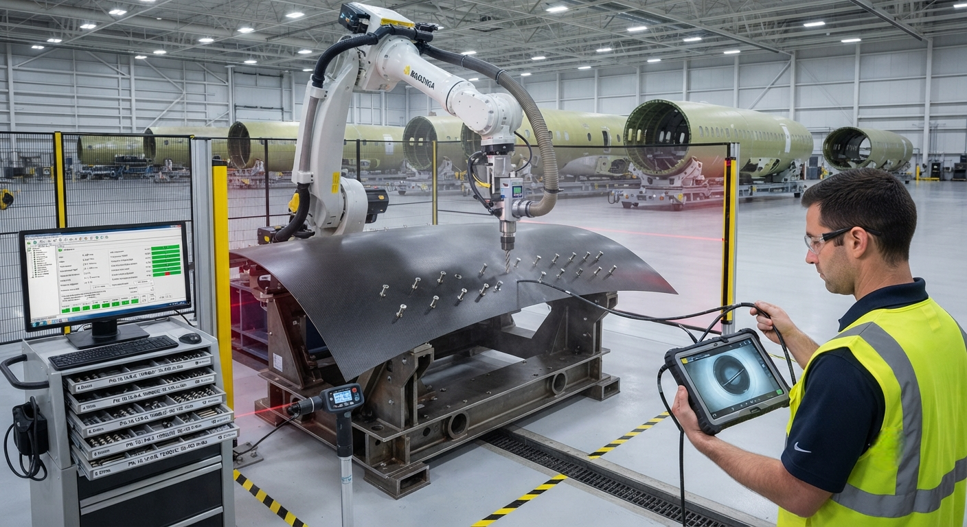
Robotic drilling systems for carbon fiber aerospace structures require precise control of spindle speed, feed rate, tool geometry, and fastener insertion parameters to achieve hole quality standards demanded by aircraft OEMs. This article examines hole quality parameters, drilling tool selection, robotic system configuration, and fastener insertion process controls for B2B aerospace manufacturing buyers.
Aer-grade carbon fiber structures present unique challenges in drilling and fastening operations. Unlike metals, composites are anisotropic and prone to delamination, fiber pull-out, thermal degradation, and matrix cracking when subjected to improper machining parameters. A single out-of-tolerance fastener hole in an aircraft wing skin or fuselage panel can require expensive rework or even scrap the entire component. With modern commercial aircraft containing 50,000 to 200,000 mechanical fasteners per airframe — the Boeing 787 alone uses approximately 60,000 Hi-Lok fasteners in its composite fuselage — the financial impact of poor hole quality is substantial.
Robotic drilling systems have become the standard solution for aerospace composite assembly, offering repeatable positioning accuracy of ±0.1 mm, feed rate control within 1 mm/min, and spindle speeds up to 20,000 RPM. These systems integrate automated drill bit change, vacuum chip extraction, and in-process hole quality inspection. This article examines the key parameters governing hole quality in robotic drilling of carbon fiber composites and the critical factors in fastener insertion processes.
Hole Quality Parameters and Measurement
Hole quality in carbon fiber composites is characterized by multiple parameters that must be simultaneously controlled. The aerospace industry typically requires hole diameter tolerances of H9 (IT grade 9) or tighter, corresponding to ±0.025 mm for a 6.4 mm diameter hole. Surface roughness Ra must be below 1.6 μm, and exit-side delamination — measured by the delamination factor Fd (ratio of maximum damaged diameter to hole diameter) — must not exceed 1.10 for primary structure applications.
| Parameter | Required Specification | Measurement Method | Common Defect When Exceeded |
|---|---|---|---|
| Hole diameter tolerance | H9 (ISO 286) — ±0.025 mm for ø6.4 mm | Air gauge or CMM probe | Fastener fit failure, reduced clamp load |
| Surface roughness Ra | ≤1.6 μm | Profilometer (contact or laser) | Fretting fatigue initiation, seal failure |
| Delamination factor Fd (entry) | ≤1.05 | Digital microscopy | Reduced bearing strength |
| Delamination factor Fd (exit) | ≤1.10 (primary) / ≤1.15 (secondary) | Digital microscopy or ultrasonic C-scan | Fatigue crack propagation from damage zone |
| Circularity error | ≤0.020 mm | CMM or vision system | Eccentric fastener loading |
| Countersink depth tolerance | ±0.050 mm | Depth indicator or laser sensor | Protruding or recessed fastener head |
| Burr height (entry) | ≤0.050 mm | Vision inspection | Interference with mating surface, FOD risk |
Drilling Parameters and Tool Selection
Successful robotic drilling of carbon fiber composites requires careful selection of cutting parameters matched to the specific composite layup, fiber orientation, and resin system. The key parameters are spindle speed (N), feed rate (f), and step drilling strategy. For typical aerospace-grade CFRP (Toray T700/3900 or equivalent), recommended starting parameters are spindle speed of 6,000 to 12,000 RPM with feed rate of 0.02 to 0.08 mm/rev. Higher spindle speeds reduce cutting forces but increase thermal exposure, risking matrix degradation at temperatures above the resin glass transition temperature (typically 160–200°C for epoxy systems).
Tool geometry is equally critical. Polycrystalline diamond (PCD) tipped drills offer the longest tool life — typically 500 to 2,000 holes per tool in CFRP — while CVD diamond-coated carbide drills provide a lower-cost alternative with 200 to 500 holes per tool. Uncoated carbide drills wear rapidly in CFRP, often lasting fewer than 100 holes. The drill point angle for CFRP is typically 90° to 120°, with a point geometry designed to minimize thrust force at exit — the primary mechanism for exit delamination. Specialized "step" drill bits with a pilot diameter followed by a reaming section reduce thrust force by up to 40% compared to conventional twist drills.
Robotic System Configuration
Modern robotic drilling cells used in aerospace assembly include these key subsystems:
- Articulated robot arm: Typically a 6-axis industrial robot with 50-200 kg payload capacity, absolute positioning accuracy of ±0.05 mm when calibrated with laser tracker, and stiffness optimized for machining operations (e.g., KUKA KR QUANTEC, Fanuc R-2000iC, ABB IRB 6700)
- Drilling end-effector: A purpose-built unit incorporating the spindle motor (2-7 kW), automatic drill bit changer with 6-12 tool capacity, pressure foot that pre-loads the drill bushing against the work surface to suppress delamination, and integrated vacuum chip extraction with HEPA filtration
- Process monitoring: Real-time thrust force monitoring via piezo-electric dynamometer, spindle power consumption monitoring for tool wear detection, and in-line hole inspection using laser profilometry or vision-based diameter measurement
- Fastener insertion station: Automated fastener delivery, sealant application (for wet installation), and torque-controlled nutrunner with angle monitoring for Hi-Lok, lockbolt, and interference-fit fastener installation
Fastener Insertion Parameters
For aerospace composite structures, fastener insertion is as critical as hole preparation. Interference-fit fasteners — where the fastener diameter exceeds the hole diameter by 0.02 to 0.08 mm — are commonly specified to improve fatigue life through compressive residual stress around the hole. However, excessive interference in CFRP can cause delamination during insertion. Controlled insertion force and rate are essential:
- Insertion force monitoring to detect galling or excessive friction indicative of hole damage
- Torque control for threaded fasteners with ±3% accuracy, with torque-angle monitoring to detect thread stripping or insufficient clamp load
- Sealant application control for wet-installed fasteners — typically a two-part polysulfide or epoxy sealant (e.g., PR-1776, Hysol EA9394) applied to the shank and countersink with ±0.5 mm bead placement accuracy
- Post-installation flushness inspection via laser profilometry to verify fastener head protrusion or countersink depth within ±0.050 mm
FAQ
What is the most common defect in robotic drilling of carbon fiber composites and how is it prevented?
Exit-side delamination is the most common and most serious defect in CFRP drilling. It occurs when the drill pusheses through the last plies without sufficient support, causing the remaining uncut plies to flex and separate. Prevention strategies include: using a backup support plate or sacrificial backing material on the exit side, employing step-drill geometry that reduces thrust force at breakthrough, optimizing feed rate reduction during the final 0.5 mm of penetration (typically reducing feed by 50-60%), and using robotic pressure foot pre-load (100-300 N) to compress the laminate before and during drilling. Process monitoring with real-time thrust force feedback allows automatic feed adjustment when force thresholds are approached.
How does robotic drilling compare to manual drilling for CFRP aerospace structures?
Robotic drilling systems offer significant advantages over manual drilling: positioning repeatability of ±0.1 mm versus ±0.5 mm for skilled operators; consistent feed rates eliminating operator-induced variations; automated chip extraction reducing foreign object debris (FOD) risk; cycle time reduction of 40-60% through optimized drilling parameters and automated tool change; integrated process monitoring enabling 100% in-process quality verification versus manual post-process inspection sampling. However, robotic systems require higher capital investment (typically $500,000-$1,500,000 per cell), significant programming effort for complex curved panels, and dedicated fixturing. For low-volume production or prototypes with fewer than 50 holes per part, manual drilling by trained operators remains competitive, particularly for non-primary structure applications.
What certification is required for robotic drilling programs on composite aerospace structures?
Robotic drilling programs for composite aerospace structures must be qualified to customer specifications derived from industry standards such as SAE AS81981 (Drilling, Reaming and Countersinking, Composite and Metallic Structures) and SAE ARP5618 (Drilling, Reaming and Fastener Installation in Composite Structures). The qualification process includes: first-article inspection of drilled holes including micrographic cross-section analysis, capability studies (Cpk ≥ 1.67 for hole diameter and countersink depth), fastener installation pull-test and torque verification, and periodic re-qualification at defined intervals (typically annually or after any change to tooling, robot, or material lot). Additionally, the robot programmer and operators must demonstrate competency through documented training programs aligned with the manufacturer's Nadecap AC7114 or AS9100 quality system requirements.
Conclusion
Robotic drilling and fastening of carbon fiber aerospace structures requires systematic control of drilling parameters, tool geometry, and fastener insertion processes to achieve the hole quality demanded by modern aircraft OEMs. By implementing proper parameter selection, real-time process monitoring, and qualified programs, manufacturers can achieve defect-free hole production at production rates that support aircraft build rates of 40-60 units per month. For B2B buyers seeking composite machined components or assembly services, verification of robotic drilling capability including Cpk studies, process monitoring data, and operator certification records is essential. Yongxian Carbon Fiber offers precision robotic drilling and fastening services for aerospace composite structures up to 15 meters in length, with in-process quality monitoring and full traceability. Contact our aerospace manufacturing team for capability discussions or process qualification support.
Part of topic
Related Articles
- Bio-Based Carbon Fiber Precursors: Lignin and Polyethylene for Low-Cost Production
- Large-Tow Carbon Fiber Cost Analysis: 48K vs 60K Price-Performance Comparison
- Carbon Fiber-Resin Interface Bonding: Surface Treatment and Coupling Agent Optimization
- Digital Twin for Carbon Fiber Manufacturing: Real-Time Process Monitoring and Defect Prevention
- Thermoplastic Carbon Fiber Welding for Automotive: Ultrasonic and Induction Welding Process Windows
- Large-Tow Carbon Fiber Wet Spinning: Process Optimization for 48K/60K Production Efficiency
Interested in Our Products?
Contact our team for competitive pricing and technical specifications.
Get a QuoteRelated Products

Custom Carbon Fiber Medical Device Components
Medical-grade carbon fiber components manufactured for imaging equipment, surgical instruments, and patient support systems. Carbon fiber's radiolucency (X-ray transparency) and high strength-to-weight ratio make it ideal for CT scanner beds, wheelchair frames, surgical robot arms, and MRI-compatible accessories. Biocompatible resin systems available.

Carbon fiber standard plate-3k stripe
Lightweight, ultra-rigid standard sheets for drone fuselages, robot housings, facades and structural applications.

Square Carbon Fiber Tube — 3K Twill T700
Square cross-section carbon fiber tube manufactured with 3K twill weave for torsional strength. Preferred for structural frames, trusses, and support columns where rectangular geometry offers design flexibility.

Carbon Fiber Plate — 3K Twill T700 3.0mm
Medium-thickness 3.0mm carbon fiber plate offering significantly higher load capacity while maintaining attractive 3K twill finish. Suitable for structural brackets, reinforcement plates, and load-bearing panels.

Carbon Fiber Plate — 3K Twill T700 1.5mm
Thin 1.5mm carbon fiber plate with 3K twill weave surface. Lightweight and stiff, commonly used for covers, panels, drone bodies, and applications requiring a premium aesthetic appearance.