
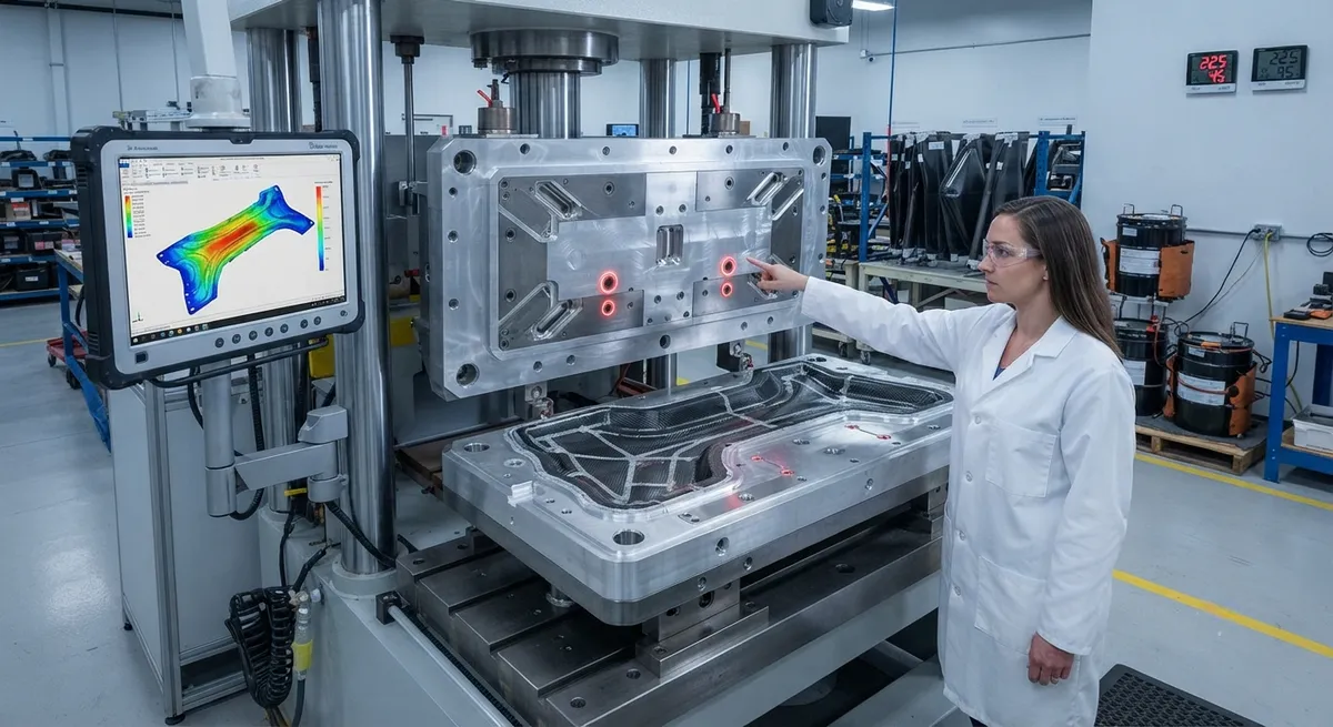
Resin Transfer Molding (RTM) process design for carbon fiber composites critically depends on injection port and vent placement to achieve void-free parts with consistent mechanical properties. This article presents simulation-guided methodology for port placement optimization using Darcy's law-based flow modeling, covering gate location strategies, vent positioning rules, and real-world case studies from automotive and aerospace production runs.
Introduction: The Void-Free Molding Challenge
Resin Transfer Molding (RTM) is one of the most widely used manufacturing processes for high-performance carbon fiber composite components in the automotive, aerospace, and marine industries. In RTM, a dry fiber preform is placed into a closed mold, and liquid thermoset resin is injected under pressure to impregnate the reinforcement. After curing, the part is demolded with net-shape geometry and high-quality surface finish on both sides. However, achieving consistently void-free parts requires meticulous design of the injection and venting system — the most critical and often underestimated aspect of RTM tooling design.
Voids in RTM parts typically originate from two mechanisms: (1) air entrapment during mold filling when the advancing resin flow front converges around obstacles or through thickness variations, and (2) micro-void formation at the fiber tow level due to competing capillary and viscous forces during dual-scale flow. Macro-voids (>100 μm) directly reduce mechanical properties, with each 1% void content reducing interlaminar shear strength by 5-10% and compressive strength by 7-15%. For Class A automotive body panels and aerospace primary structures, void content must be maintained below 1% and typically below 0.5% for critical applications. This technical article presents a systematic, simulation-guided methodology for injection port and vent placement that has been validated across hundreds of production RTM tools.
Darcy's Law and Flow Front Modeling
The fundamental physics governing resin flow through fibrous reinforcements in RTM is described by Darcy's law for flow through porous media. For a one-dimensional flow, the volumetric flow rate Q is proportional to the permeability K of the preform, the cross-sectional area A, and the pressure gradient ΔP/L, divided by the resin viscosity μ. In practical RTM simulation, the three-dimensional form of Darcy's law is solved numerically using finite element or finite volume methods to predict the resin flow front progression, pressure distribution, and fill time across the mold cavity. Commercially available simulation packages such as PAM-RTM, RTM-Worx, and LIMS use control volume finite element (CV/FE) approaches coupled with automated mesh refinement around injection ports and vent locations for accurate local pressure and saturation predictions.
| Simulation Parameter | Typical Range | Impact on Port Placement |
|---|---|---|
| Preform Permeability (K) | 1×10⁻¹⁰ to 1×10⁻⁸ m² | Determines flow resistance; lower permeability requires more injection ports |
| Resin Viscosity (μ) | 0.05-1.0 Pa·s at injection temperature | Higher viscosity increases pressure drop; may limit maximum flow distance from each port |
| Injection Pressure | 0.1-10 bar (low-pressure RTM) 10-100 bar (HP-RTM) | Higher pressure allows fewer ports but increases tooling cost and fiber washout risk |
| Fiber Volume Fraction | 45-65% | Higher FVF reduces permeability; requires denser port spacing |
| Part Thickness | 1-10 mm typical | Thicker sections act as flow channels; vents needed at thick-to-thin transitions |
| Injection Temperature | 40-120°C | Controls resin viscosity window; affects gel time management |
Injection Port Placement Strategies
The selection and positioning of injection ports (also called gates or inlets) follow several fundamental principles derived from flow simulation analysis. The primary objective is to achieve a controlled, progressive flow front that pushes air ahead of the resin toward the vent locations, minimizing the risk of air entrapment and dry spot formation.
- Edge Injection vs. Center Injection: Edge injection places ports along the mold periphery and is preferred for thin, flat parts with high length-to-width aspect ratios. Center injection places a single port at the geometric center and is effective for thick, symmetrical parts where radial flow promotes uniform fill. For complex geometries, a hybrid approach with 2-6 ports distributed across the part surface is common.
- Flow Distance Limitation: Each injection port can effectively impregnate a maximum flow distance of 300-800 mm depending on preform permeability, resin viscosity, and injection pressure. Beyond this distance, the pressure gradient becomes insufficient to maintain adequate flow velocity, leading to premature gelation and incomplete fill. For high-performance epoxy systems with 30-60 minute gel time at 80°C, maximum flow distance is typically limited to 500 mm for 55% FVF quasi-isotropic carbon fiber preforms.
- Gate Geometry: Injection port geometry significantly affects local flow behavior. Point gates (2-5 mm diameter) create radial flow patterns and are suitable for small to medium parts. Line gates (slot-type, 10-100 mm length) produce linear flow fronts and are used for long, narrow parts such as automotive crash rails and structural beams. Fan gates distribute resin across a wider area and are preferred for thin-walled parts (1-3 mm thickness) where high injection rates would otherwise cause fiber washout.
- Position Relative to Inserts and Thickness Changes: Injection ports must be positioned upstream of metal inserts, core materials, and thickness transitions. Flow simulation consistently shows that placing the injection point in the thickest section of the part allows resin to fill thin sections progressively, preventing premature flow front pinching and void formation around corners and ribs.
- Number of Ports Optimization: Multi-port injection systems require careful timing and sequencing. Simultaneous injection from all ports can create multiple flow fronts that meet at weld lines, trapping air between them. Sequential injection, where ports are opened in a controlled sequence as the flow front advances, is the preferred strategy for parts with complex geometry or large surface area exceeding 1 m².
Vent Placement Rules
Vent positioning in RTM tooling is arguably more critical than injection port placement because improperly placed vents cannot be compensated for by increased injection pressure or modified injection strategy — the vent locations are fixed once the tool is manufactured. Effective vent placement follows a hierarchy of priority rules derived from both simulation and empirical production data.
The highest priority locations for vents are: (1) the last areas to fill, as identified by flow simulation; (2) geometric high points on the part surface; (3) transitions from thick to thin sections; (4) corners, ribs, and bosses where flow front convergence is likely; and (5) the far end of the mold cavity relative to the injection ports. For each injection port, at least one dedicated vent should be positioned at the farthest flow distance to ensure complete air evacuation. In practice, production RTM tools incorporate 1.5-2.5 vents per injection port, with additional vents distributed at geometric features prone to air entrapment.
| Part Feature | Vent Type | Recommended Quantity | Vent Gap (mm) | Position Rule |
|---|---|---|---|---|
| Flat panel (1-3 mm) | Peripheral groove vent | 2-4 per mold half | 0.05-0.15 | Mold parting line, 10-20 mm from cavity edge |
| Rib feature | Pin vent at rib tip | 1 per rib termination | 0.08-0.20 | At the tip of each rib, on the mold side |
| Boss/insert | Annular ring vent | 1 per insert | 0.10-0.25 | Circumferential around each boss at 2-5 mm radial offset |
| Thickness step change | Slot vent on thin side | 1 per 100 mm transition length | 0.05-0.12 | Immediately downstream of the thickness reduction |
| Complex 3D geometry | Individual port vent | 1.5-2.5 per injection port | 0.10-0.30 | At all last-to-fill locations from simulation |
Case Study: Automotive Structural B-Pillar
A significant validation of simulation-guided port placement comes from the production of a carbon fiber B-pillar reinforcement for a high-volume electric vehicle platform. The part measures 1,200 × 350 mm with a nominal thickness of 2.5 mm, featuring two rib structures, four mounting bosses, and a thickness transition from 2.5 mm to 4.0 mm at the roof interface. Initial tooling with a single center injection port and four peripheral vents produced parts with an average void content of 2.3%, far exceeding the 0.5% maximum for the application. Flow simulation identified the root cause: the center injection port created a radial flow front that reached the part edges at different times, with air trapped at the rib terminations and around the bosses where flow fronts converged at 90-degree angles.
The optimized tooling design replaced the single center port with three injection ports positioned along the part centerline — one at the geometric center and one 200 mm from each end. A total of six vents were added: two at the rib terminations, one at each of the four boss locations, and two at the far edges. The optimized configuration, validated by simulation and production trials, reduced average void content to 0.3% (measured by ultrasonic C-scan and cross-sectional microscopy on 50 production parts). The fill time decreased from 210 seconds to 145 seconds, and the scrap rate for void-related defects dropped from 8.5% to 0.7%. This case demonstrates that a single simulation-guided redesign of port and vent placement can simultaneously improve quality, reduce cycle time, and lower manufacturing cost.
FAQ
Can RTM simulation accurately predict dry spot formation?
Yes, modern RTM flow simulation packages can predict dry spot (air entrapment) formation with 85-95% accuracy when the preform permeability is properly characterized and the resin cure kinetics are well understood. The main sources of prediction error are permeability variation within the preform (typically ±15-25% for woven fabrics) and local fiber compression effects at mold closures and inserts. State-of-the-art simulation incorporates stochastic permeability fields to provide probabilistic void formation maps, allowing tool designers to place vents with quantified confidence levels. For critical aerospace applications, simulation-guided vent placement is typically validated by a short-shot trial program where injection is deliberately stopped at 50%, 75%, and 90% fill, allowing direct comparison of predicted and actual flow front positions.
What is the optimal vent gap for carbon fiber RTM?
The optimal vent gap depends on the fiber architecture and resin system. For woven carbon fiber fabrics (2×2 twill, 5-harness satin), the recommended vent gap is 0.05-0.15 mm. This gap is small enough that surface tension prevents resin from escaping under typical injection pressures of 2-5 bar, yet large enough to allow air evacuation. For unidirectional (UD) preforms, the higher permeability along the fiber direction allows slightly larger vent gaps of 0.10-0.20 mm. For HP-RTM processes with injection pressures of 50-100 bar, vent gaps must be reduced to 0.03-0.08 mm to prevent resin leakage, often requiring vacuum-assisted venting to ensure complete air removal at these tighter clearances.
How does YongXian CarbonFiber support RTM process optimization?
YongXian CarbonFiber supplies a comprehensive range of carbon fiber reinforcements engineered for RTM processing, including 2×2 twill fabrics, unidirectional non-crimp fabrics (NCF), and multiaxial stitched fabrics with optimized binder content for preform handling. Our technical team provides permeability data sheets for each reinforcement type — a critical input parameter for RTM flow simulation. We also offer 3D preforming solutions with tailored binder patterns that maintain fiber architecture during injection. Contact our applications engineering team for permeability characterization data and material selection guidance for your specific RTM tool design.
Part of topic
Related Articles
- Bio-Based Carbon Fiber Precursors: Lignin and Polyethylene for Low-Cost Production
- Large-Tow Carbon Fiber Cost Analysis: 48K vs 60K Price-Performance Comparison
- Carbon Fiber-Resin Interface Bonding: Surface Treatment and Coupling Agent Optimization
- Digital Twin for Carbon Fiber Manufacturing: Real-Time Process Monitoring and Defect Prevention
- Thermoplastic Carbon Fiber Welding for Automotive: Ultrasonic and Induction Welding Process Windows
- Large-Tow Carbon Fiber Wet Spinning: Process Optimization for 48K/60K Production Efficiency
Interested in Our Products?
Contact our team for competitive pricing and technical specifications.
Get a QuoteRelated Products

Carbon fiber standard plate-3k stripe
Lightweight, ultra-rigid standard sheets for drone fuselages, robot housings, facades and structural applications.

Carbon Fiber Plate — 3K Twill T700 3.0mm
Medium-thickness 3.0mm carbon fiber plate offering significantly higher load capacity while maintaining attractive 3K twill finish. Suitable for structural brackets, reinforcement plates, and load-bearing panels.

Carbon Fiber Plate — 3K Twill T700 1.5mm
Thin 1.5mm carbon fiber plate with 3K twill weave surface. Lightweight and stiff, commonly used for covers, panels, drone bodies, and applications requiring a premium aesthetic appearance.

Custom Carbon Fiber Medical Device Components
Medical-grade carbon fiber components manufactured for imaging equipment, surgical instruments, and patient support systems. Carbon fiber's radiolucency (X-ray transparency) and high strength-to-weight ratio make it ideal for CT scanner beds, wheelchair frames, surgical robot arms, and MRI-compatible accessories. Biocompatible resin systems available.

Square Carbon Fiber Tube — 3K Twill T700
Square cross-section carbon fiber tube manufactured with 3K twill weave for torsional strength. Preferred for structural frames, trusses, and support columns where rectangular geometry offers design flexibility.