
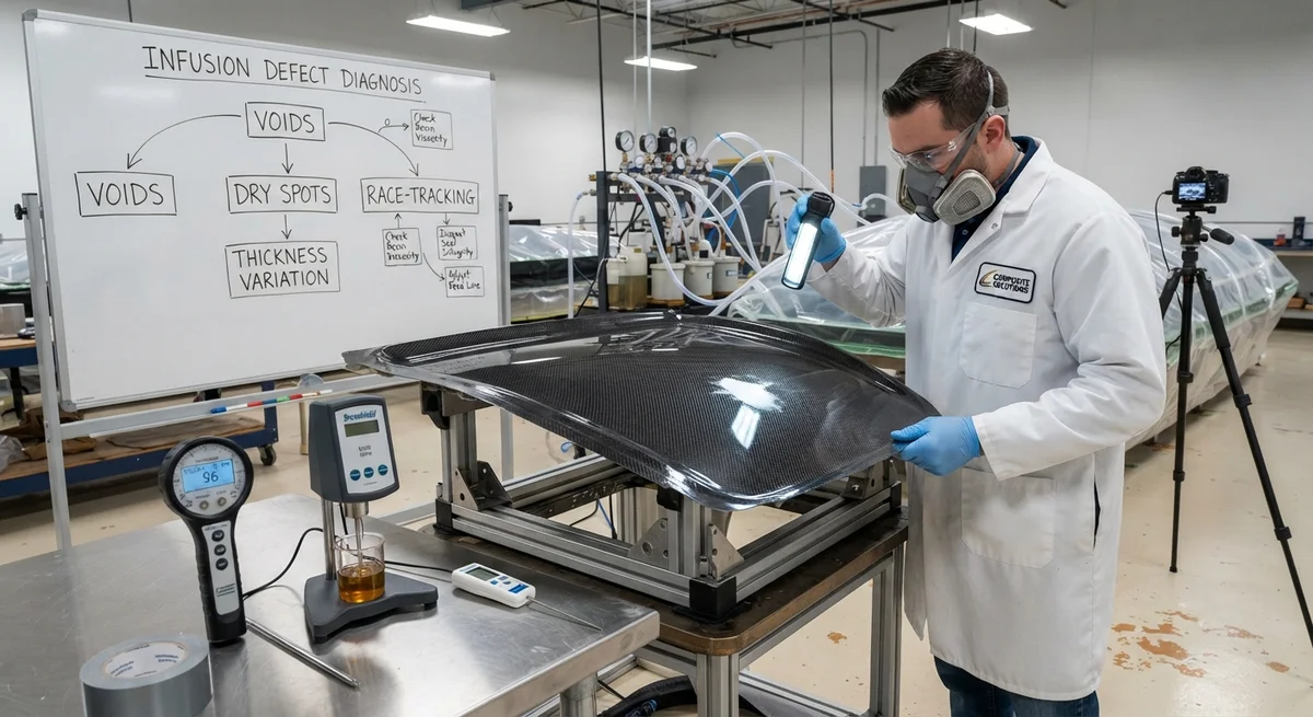
A practical troubleshooting guide for resin infusion of carbon fiber parts, covering root causes and corrective actions for voids, dry spots, race-tracking, and thickness variation with diagnostic flowcharts.
Introduction: The Economics of Infusion Defects
Resin infusion — also known as vacuum-assisted resin transfer molding (VARTM) — is the dominant manufacturing process for large carbon fiber composite parts in the marine, wind energy, and transportation sectors. A single infusion of a 40-meter wind turbine blade or a 20-meter yacht hull can consume 500–2,000 kg of resin and 1,000–8,000 person-hours of labor. When an infusion generates defects — voids, dry spots, race-tracking channels, or thickness variation — the entire part may be scrapped or require expensive post-infusion repair. Industry data indicates that infusion-related defects account for 18–25% of composite manufacturing scrap costs in the wind energy sector, and 12–18% in marine production. This article provides a structured troubleshooting methodology for the most common infusion defects, based on root cause analysis and corrective action protocols used by commercial composite manufacturers.
Defect Classification and Diagnostic Framework
Resin infusion defects can be classified into four primary categories based on their manifestation in the cured laminate. Each category has distinct root causes and corrective actions, though defects often occur in combination.
| Defect Category | Visual Appearance | Typical Location | Frequency in Production | Severity (1–5) |
|---|---|---|---|---|
| Voids (gas entrapment) | Spherical or elongated cavities visible on cut surfaces or in micrographs | Thick sections, ply drops, corners | 25–40% of infusions | 4 |
| Dry spots (incomplete wet-out) | White, uninfused fiber regions visible through vacuum bag | Distal ends, behind obstructions, thick/thin transitions | 10–20% of infusions | 5 |
| Race-tracking (preferential flow) | Resin flows rapidly along edges or channels, leaving central areas unfilled | Laminate edges, core material cut edges, stiffener intersections | 30–50% of infusions | 3 |
| Thickness variation / fiber wash | Non-uniform laminate thickness; fiber distortion or misalignment | High-flow areas, infusion inlet/outlet zones | 15–25% of infusions | 3 |
1. Voids: Root Causes and Corrective Actions
Voids are gas-filled cavities within the cured laminate that reduce mechanical properties — particularly interlaminar shear strength (ILSS) and compression strength. A 1% increase in void content reduces ILSS by approximately 7% and compression strength by 10% in carbon/epoxy systems. Voids are classified as either macro-voids (>50 µm, visible to the naked eye) or micro-voids (<50 µm, requiring microscopy).
Root Causes
- Insufficient vacuum level: Vacuum pressure below 85 kPa (absolute) — recommended minimum for carbon fiber infusion is 95–98 kPa (absolute). Every 5 kPa reduction in vacuum level increases equilibrium void content by 0.3–0.5%.
- Resin degassing insufficient: Mixed resin held at vacuum for less than 10–15 minutes before infusion begins. Dissolved air content in undegassed epoxy can be 3–8% by volume at 25°C.
- Tack too high (cold resin): Resin viscosity above 400 cP at infusion temperature. Ideal viscosity range for carbon fiber infusion is 150–350 cP. At 450+ cP, air bubble mobility through the fiber preform drops by 60%.
- Fiber preform compaction too low: Fiber volume fraction below 48% in the infused region, leaving large inter-tow channels where air can be trapped. Target FVF: 50–55% for standard infusion.
- Outgassing from core materials: PVC or PET foam core outgassing when exposed to vacuum (common with low-density foams <80 kg/m³). Core material should be pre-conditioned at 60°C under vacuum for 2–4 hours before infusion.
Corrective Actions
- Verify vacuum level with a calibrated gauge at the resin trap — not at the pump. Minimum 95 kPa (absolute) at the far end of the part.
- Degas mixed resin for 15–20 minutes at 95+ kPa vacuum before infusion. For epoxy systems with >60-minute pot life, degas at 40–50°C to accelerate bubble rise.
- Preheat resin to 30–40°C (within manufacturer's recommended range) to reduce viscosity to 200–300 cP.
- Increase compaction: apply 95+ kPa vacuum for 30–60 minutes before starting resin flow. Use a breather layer sequence that provides uniform compaction across all sections.
- For foam-cored parts: pre-vacuum core material at 60°C for minimum 2 hours. Use closed-cell foam with density >100 kg/m³ for vacuum infusion applications.
| Vacuum Level (kPa absolute) | Equilibrium Void Content (%) | ILSS Reduction vs Zero-Void | Advice |
|---|---|---|---|
| 98–100 | <0.5 | 0–3% | Excellent — target range |
| 95–97 | 0.5–1.0 | 3–7% | Acceptable for most parts |
| 90–94 | 1.0–2.0 | 7–14% | Marginal — investigate leak sources |
| 85–89 | 2.0–3.5 | 14–25% | Poor — stop infusion and repair vacuum system |
| <85 | >3.5 | >25% | Unacceptable — part likely scrap |
2. Dry Spots: Root Causes and Corrective Actions
Dry spots — regions where the resin fails to wet out the carbon fiber reinforcement — are the most expensive infusion defect because they often render the entire part unusable. They typically manifest as white or light-colored patches visible through the vacuum bag during infusion, or discovered only after demolding.
Root Causes
- Insufficient resin flow front velocity: Resin gel time exceeded before complete fill. For a 15-minute gel-time epoxy at 25°C, the maximum allowable flow distance at 1 cm/min flow front velocity is 15 cm from the last inlet. Larger parts require faster-catalyzed resin at multiple injection points.
- Race-tracking starvation: Preferential flow along an edge channel starves the adjacent laminate of resin, leaving a dry region parallel to the channel.
- Permeability barrier: A layer of fabric with significantly lower permeability (e.g., a dense veil or a pre-cured patch) blocks resin flow to downstream layers.
- Vacuum bag bridging (tenting): The vacuum bag bridges over a contoured feature (sharp corner, tight radius, or edge of a core insert), creating a low-compaction zone that increases local permeability and diverts flow.
- Resin viscosity too high: At viscosities above 500 cP, the resin cannot penetrate dense fiber architectures (e.g., >600 g/m² unidirectional fabrics) within the available gel time window.
Corrective Actions
- Add supplemental injection ports in the dry spot region for subsequent infusions. A rule of thumb: maximum flow distance from any injection port should not exceed 40 cm for unidirectional laminates, or 60 cm for ±45° biaxial laminates.
- Install flow-enhancement media (green flow mesh or perforated release film) over the entire laminate surface. A layer of 0.5–1.0 mm thick flow mesh increases in-plane permeability by 3–5×.
- Reduce resin viscosity by warming to 35–40°C. Every 10°C temperature increase halves the viscosity of standard epoxy infusion systems.
- For severe bridging: add pleats or folds in the vacuum bag at contour transitions; use a thicker (0.2 mm) release film that conforms better; or switch to a female mold configuration.
- Use sequential injection: open upstream ports first, then open downstream ports as the resin front approaches, maintaining a continuous flow front.
3. Race-Tracking: Root Causes and Corrective Actions
Race-tracking — also called preferential flow or channeling — occurs when resin flows significantly faster along a low-resistance path (typically at laminate edges, core-to-skin interfaces, or stiffener intersections) than through the bulk of the fiber preform. This creates a resin-rich channel on the fast path while the main laminate area fills slowly or incompletely.
Root Causes
- Excessive gap at laminate edges: The gap between the fiber preform and the mold edge-tool or vacuum bag seal is more than 3–5 mm. Resin flow velocity through an open gap is approximately 50–100× faster than through a 55% FVF carbon preform.
- Core material cut edges: Unsealed foam or balsa core edges create open channels along the core surface. The saw-cut cells of a 6 mm PVC foam core provide a continuous open channel with roughly 20× the permeability of the carbon preform.
- Inconsistent compaction: Low compaction zones along edges (due to bag bridging) allow the fiber preform to spring back, creating a low-FVF region with 3–5× higher permeability.
- Flow media edge exposure: Flow enhancement media extending beyond the laminate boundary at the edge creates a direct resin short-circuit from inlet to outlet.
| Race-Tracking Source | Typical Flow Velocity Ratio (vs Laminate Bulk) | Corrective Action | Cost Impact |
|---|---|---|---|
| Edge gap >5 mm | 50–100× | Use edge dams (caulk or preformed seal) to close gap to <2 mm | Low — consumable cost <$5/m |
| Unsealed core edge | 15–30× | Apply core edge sealant (body filler or thickened resin) before layup | Moderate — 0.5–1.0 hr labor per m² |
| Bag bridging at corner | 5–15× | Add bag pleats; use conformable release film; increase corner radius | Low — design change |
| Flow media overhang | 30–80× | Cut flow media 5–10 mm inside laminate edge; use edge bleeder only | Low — consumable trim time |
Corrective Actions
- Install edge dams (tacky tape or pre-formed silicone dams) at all laminate edges to prevent preferential edge flow. Gap should be <2 mm between preform and dam.
- Apply core edge sealant (automotive body filler or epoxy with thickening filler) to all foam/balsa cut edges before layup. Allow 2–4 hours cure time before infusion.
- Cut flow enhancement media 5–10 mm inside the laminate perimeter to prevent resin from short-circuiting around the edge.
- For complex geometries with multiple core transitions: divide the infusion into zones with individual injection ports and independent flow control (sequential injection).
4. Thickness Variation and Fiber Wash
Thickness variation — non-uniform laminate thickness across the part — and fiber wash — displacement of fibers from their intended orientation — are flow-related defects caused by uneven resin pressure distribution during infusion. These defects are particularly problematic in applications with tight dimensional tolerances (aerospace tooling, automotive body panels) and where fiber orientation accuracy is critical (structural beams, pressure vessels).
| Flow Condition | Effect on Thickness | Effect on Fiber Orientation | FVF Variation |
|---|---|---|---|
| Inlet zone (high resin pressure) | +5–15% (thicker) | Fiber washing: 5–15° misalignment | −5–10% |
| Mid-field (steady flow) | ±2–5% | Minimal (<2°) | ±2% |
| Outlet zone (low resin pressure) | −5–10% (thinner) | Fiber compaction, minimal wash | +3–8% |
| Race-track channel adjacent | −10–20% (thinner) | Fiber draw into channel: 10–30° misalignment | +5–15% |
Corrective Actions
- Use multiple injection points to reduce the maximum flow distance and equalize pressure distribution. Target: maximum flow distance <50 cm per inlet.
- Control injection pressure: start at 20–40 kPa (absolute) at the inlet, gradually reducing to 95+ kPa vacuum at the outlet. A pressure gradient that is too steep causes fiber washing at the inlet; too shallow causes slow fill and gel-time issues.
- Use a distribution medium system (two layers of flow mesh for thick laminates) to spread the resin pressure evenly across the part width.
- For parts requiring tight thickness tolerance (±0.1 mm): use hard caul plates over the laminate surface to maintain uniform compaction pressure.
Systematic Troubleshooting Flowchart
When a defect is observed, follow this diagnostic sequence:
- Identify the defect type: Void, dry spot, race-tracking, or thickness variation. Document position, size, frequency, and the laminate region affected.
- Check the vacuum system first: 60% of infusion defects are traced to vacuum system issues. Verify: pump vacuum level (target 98+ kPa absolute), line integrity (no leaks), resin trap condition, and seal tape continuity.
- Review the resin parameters: Temperature, viscosity, gel time, and degassing time. Compare against the manufacturer's technical data sheet for the specific batch.
- Inspect the preform: Verify fiber placement, ply orientation, core material condition, edge sealant application, and compaction uniformity.
- Analyze the flow pattern: Review video or time-lapse photos of the infusion (recommended for every production infusion). Identify where the flow front deviated from the expected pattern.
- Implement corrective action: Apply the specific corrective action for the identified root cause. Document the change and verify on the next infusion.
Frequently Asked Questions
Q: What is the minimum acceptable vacuum level for carbon fiber resin infusion?
A: The minimum acceptable vacuum level is 95 kPa (absolute), measured at the furthest point from the vacuum pump. Vacuum levels between 95–100 kPa (absolute) correspond to 0.5–1.0% equilibrium void content, which is acceptable for most structural applications. Levels below 90 kPa produce void content above 2%, which significantly degrades mechanical properties. For critical aerospace-grade components, a vacuum level of 97+ kPa is required, targeting void content below 0.5%. Note that altitude affects achievable vacuum — at 1,000 m elevation, a rotary vane pump achieves approximately 93–95 kPa absolute, versus 98–100 kPa at sea level.
Q: How do I distinguish between a void from entrapped air and a void from resin volatiles?
A: Voids from entrapped air are typically spherical, distributed randomly through the laminate, and more numerous in thicker sections. Voids from resin volatiles (outgassing of the resin system itself) are elongated or irregular, concentrated along the laminate mid-plane, and often connected by micro-cracks in the resin. The definitive diagnostic test is differential scanning calorimetry (DSC): if voids correlate with an exothermic peak above 200°C, the resin system exothermed and boiled low-molecular-weight volatiles. If no exothermic anomaly is present, the voids are from mechanical air entrapment. A practical field test: if the voids are accompanied by a strong amine odor in the cured part, the resin likely exothermed excessively.
Q: Can dry spots be repaired in cured parts, or must the part be scrapped?
A: Small dry spots (<25 cm²) in non-critical areas can be repaired by: (1) drilling 1–2 mm diameter injection holes through the dry region; (2) applying vacuum to the back side of the part to draw low-viscosity resin (the same infusion resin) through the dry fibers; and (3) curing under local vacuum bag or pressure pad. For dry spots larger than 25 cm², or in structurally critical zones (load-bearing laminate sections, bond lines, or areas subject to fatigue loading), the part should be scrapped. The repair area's ILSS is typically 50–70% of the parent laminate, and the repair introduces a non-uniform stress field that becomes a fatigue initiation site. Ultrasonic C-scan is recommended to verify the repair quality.
Q: What is the ideal resin viscosity for carbon fiber infusion?
A: The ideal resin viscosity for carbon fiber infusion is 200–350 cP at the injection temperature. At this viscosity range, the resin flows readily through the fiber preform (permeability K = 1×10⁻¹¹ to 1×10⁻¹⁰ m² for a standard ±45° biaxial carbon fabric at 52% FVF) while maintaining sufficient resistance to prevent race-tracking. Resin viscosity below 150 cP leads to excessive race-tracking along any available edge gap. Viscosity above 450 cP increases void content and reduces maximum flow distance by approximately 40% per 100 cP increase. Measure viscosity with a Brookfield viscometer at the actual infusion temperature before each production run.
Q: How do I determine the optimal number and position of injection ports?
A: The optimal injection port layout depends on the part geometry, fiber architecture, flow enhancement media, and resin gel time. A practical methodology: (1) Calculate the maximum allowable flow distance: D_max = V_gel × t_gel, where V_gel is the expected flow front velocity (typically 0.5–2.0 cm/min) and t_gel is the resin gel time at the infusion temperature. (2) Divide the part into zones where every point is within D_max of an injection port. (3) Position ports at the lowest elevation points of the part (gravity assists flow) and avoid placing ports directly over thick-to-thin transitions. (4) For parts larger than 4 m², use sequential injection — open downstream ports only when the resin front is within 20 cm. This prevents race-tracking from multiple ports competing for flow.
Conclusion
Resin infusion defects — voids, dry spots, race-tracking, and thickness variation — are controllable through systematic process management. The data show that 60% of defects trace back to vacuum system issues, 20% to resin parameters, 15% to preform preparation, and 5% to mold design. For B2B buyers evaluating carbon fiber component suppliers, the key indicators of process maturity are: (1) documented vacuum verification protocol with calibrated gauges at multiple points; (2) resin viscosity and gel-time testing before every production infusion; (3) time-lapse video recording of every infusion for post-event analysis; (4) edge-seal and core-edge preparation procedures with quality sign-off; and (5) a defect database with root cause analysis for each occurrence. Suppliers with these practices consistently achieve first-pass yield above 92% in infusion production, compared to industry average of 75–85%.
Related Articles
- Bio-Based Carbon Fiber Precursors: Lignin and Polyethylene for Low-Cost Production
- Large-Tow Carbon Fiber Cost Analysis: 48K vs 60K Price-Performance Comparison
- Carbon Fiber-Resin Interface Bonding: Surface Treatment and Coupling Agent Optimization
- Digital Twin for Carbon Fiber Manufacturing: Real-Time Process Monitoring and Defect Prevention
- Thermoplastic Carbon Fiber Welding for Automotive: Ultrasonic and Induction Welding Process Windows
- Large-Tow Carbon Fiber Wet Spinning: Process Optimization for 48K/60K Production Efficiency
Interested in Our Products?
Contact our team for competitive pricing and technical specifications.
Get a QuoteRelated Products

Carbon fiber standard plate-3k stripe
Lightweight, ultra-rigid standard sheets for drone fuselages, robot housings, facades and structural applications.

Carbon Fiber Plate — 3K Twill T700 1.5mm
Thin 1.5mm carbon fiber plate with 3K twill weave surface. Lightweight and stiff, commonly used for covers, panels, drone bodies, and applications requiring a premium aesthetic appearance.

Square Carbon Fiber Tube — 3K Twill T700
Square cross-section carbon fiber tube manufactured with 3K twill weave for torsional strength. Preferred for structural frames, trusses, and support columns where rectangular geometry offers design flexibility.

Carbon Fiber Plate — 3K Twill T700 3.0mm
Medium-thickness 3.0mm carbon fiber plate offering significantly higher load capacity while maintaining attractive 3K twill finish. Suitable for structural brackets, reinforcement plates, and load-bearing panels.

Carbon Fiber Plate — UD Unidirectional T700
Unidirectional carbon fiber plate with all fibers oriented in a single direction for maximum strength along the fiber axis. Essential for structural reinforcements, splints, and applications where load direction is predictable.