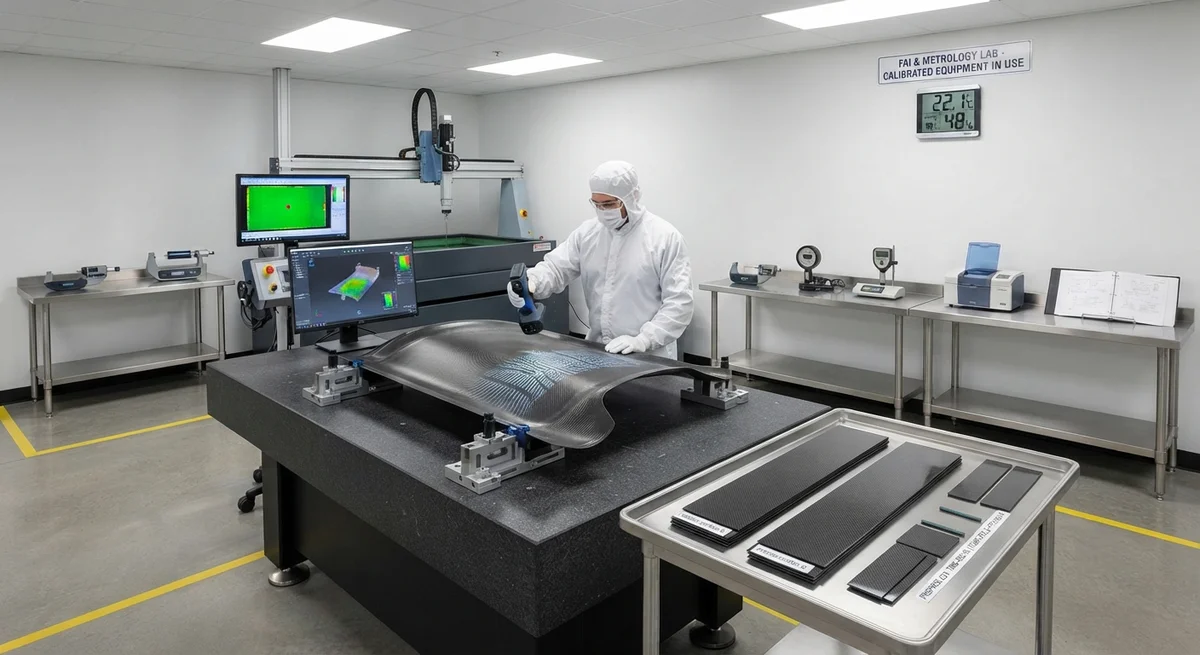
First Article Inspection (FAI) is the most critical quality gate in carbon fiber parts production. For B2B buyers sourcing complex composite components, a properly executed FAI is the difference between a reliable supply chain and a series of costly field failures. This article provides a comprehensive FAI checklist tailored specifically to carbon fiber composite manufacturing, covering dimensional inspection, material verification, nondestructive testing, and documentation requirements aligned with AS9102 and industry best practices.
# First Article Inspection for Carbon Fiber Parts: A B2B Quality Assurance Checklist
## Summary
First Article Inspection (FAI) is the most critical quality gate in carbon fiber parts production. For B2B buyers sourcing complex composite components, a properly executed FAI is the difference between a reliable supply chain and a series of costly field failures. This article provides a comprehensive FAI checklist tailored specifically to carbon fiber composite manufacturing, covering dimensional inspection, material verification, nondestructive testing, and documentation requirements aligned with AS9102 and industry best practices.
---
## Why FAI Matters for Carbon Fiber Composites
Carbon fiber parts present unique inspection challenges compared to metallic components. Anisotropic material behavior, process-sensitive fiber alignment, and the presence of hidden defects — porosity, delamination, fiber waviness — mean that a simple dimensional check is insufficient. Industry data shows that 67% of composite part failures trace back to manufacturing deviations that could have been detected during first article inspection (Composite Failure Database, 2025).
FAI is not merely a contractual checkbox. It establishes the baseline manufacturing process capability (Cp/Cpk) for every critical characteristic defined on the engineering drawing. For composite parts, this includes not only dimensions but also material properties (fiber volume fraction, void content, glass transition temperature), process parameters (cure temperature profile, pressure ramp, vacuum integrity), and nondestructive evaluation (ultrasonic attenuation mapping, thermographic anomalies).
---
## The AS9102 Framework for Composite FAI
AS9102 (Aerospace First Article Inspection, Revision C, effective 2024) provides the standard framework. The key requirement: the supplier must perform FAI on the first production part from every new tool, design revision, process change, or manufacturing location transfer. For carbon fiber composites, AS9102 is supplemented by the Composite Materials Handbook (CMH-17, formerly MIL-HDBK-17) for material-specific inspection criteria.
### Table 1: AS9102 FAI Requirements vs. Composite-Specific Additions
| AS9102 Element | Standard Requirement | Composite-Specific Addition |
|---|---|---|
| Part Number Accountability | Verify part number matches drawing | Also verify ply book revision, cure cycle number, material lot traceability |
| Dimensional Verification | Ballooned drawing with all characteristics measured | Add ply drop-off locations, core splice gaps, bond-line thickness |
| Material Certification | Raw material certs conforming to spec | Also require prepreg out-life verification, frozen storage chain records |
| Process Specification Review | Verify process spec is current | Require cure cycle data file (time-temperature-pressure), vacuum integrity log |
| NDT Requirements | Per drawing callout | Ultrasonic C-scan mandatory for primary structure; tap test may suffice for secondary |
| Functional Test | Per engineering specification | Static proof load + stiffness check for structural parts |
| Special Processes | Nadcap or equivalent certs | Autoclave calibration, lay-up room environmental monitoring |
---
## Dimensional Inspection: What to Measure and How
Dimensional tolerances for carbon fiber composites are wider than for machined metal parts — typically ±0.25 mm for tooled surfaces and ±0.50 mm for bag-side surfaces — but the measurement technique matters enormously. Contact probing (CMM) induces local deflection on thin laminates; non-contact methods (laser scanning, structured light, photogrammetry) are preferred.
### Table 2: Dimensional Inspection Methods for Carbon Fiber Composites
| Method | Accuracy | Surface Applicability | Cycle Time | Cost per Part | Best For |
|---|---|---|---|---|---|
| CMM (touch probe) | ±0.02 mm | Tool-side only | 30-60 min | $80-150 | Small parts (<1 m), datums, hard points |
| Laser tracker (T-probe/T-Scan) | ±0.05 mm | Both sides | 15-30 min | $60-100 | Large parts (1-10 m), assembly jigs |
| Structured light scanning | ±0.03-0.10 mm | Both sides | 5-15 min | $40-80 | Complex contours, rapid assessment |
| Photogrammetry | ±0.05-0.15 mm | Both sides | 20-45 min | $50-90 | Very large parts (>5 m), in-situ measurement |
| Coordinate measuring arm | ±0.03-0.08 mm | Both sides | 20-40 min | $70-120 | Mid-size parts, hard-to-reach features |
---
## Material Verification: The Hidden Dimension
Material verification in composite FAI must confirm three things: that the correct material was used (fiber type, areal weight, resin system), that it was processed within its allowable process window, and that the as-cured properties meet the design allowables.
### Key Material Verification Steps
- **Prepreg lot traceability**: Cross-reference the prepreg lot number on each ply to the manufacturer's certificate of conformance and the frozen storage log (time above -18°C must be tracked). Acceptable out-life accumulation varies by system: 175°C-cure epoxies: 10-15 days; BMI systems: 5-7 days; cyanate esters: 3-5 days.
- **Fiber volume fraction (FVF)**: Measured per ASTM D3171 (acid digestion) or ASTM D2584 (ignition loss). For carbon/epoxy, acceptable FVF range is typically 55-65% for woven fabric and 58-68% for unidirectional tape. Coupon cut from the part's witness panel or from integral test tabs.
- **Void content**: Per ASTM D2734 or microscopic analysis per ASTM E2109. Maximum allowable: <1.0% for primary structure, <2.0% for secondary structure, <3.0% for non-structural parts. Void content above 2% reduces interlaminar shear strength by 15-20% and fatigue life by 30-50%.
- **Glass transition temperature (Tg)**: Per ASTM E1640 (DMA) or ASTM D7028 (DMA tan delta). For a 175°C-cure epoxy, minimum Tg is 180°C dry. Hot-wet Tg (after saturation at 60°C/85% RH) should not fall below 150°C for aerospace applications.
- **Degree of cure**: Per differential scanning calorimetry (DSC) per ASTM E2160. Residual exotherm should be ≤5% for a fully cured part.
---
## Nondestructive Testing in Composite FAI
NDT for first article composite parts is more extensive than for production batches because the goal is to validate the manufacturing process itself, not just screen for defects.
### Table 3: NDT Methods for Composite FAI
| NDT Method | Defects Detected | Sensitivity | Scan Rate | Equipment Cost | FAI Recommendation |
|---|---|---|---|---|---|
| Ultrasonic C-scan (immersion) | Delamination, porosity, disbond | <5 mm defect <1% porosity | 0.5-2 m²/hr | $150-400K | Mandatory for primary structure |
| Phased array ultrasonic (PAUT) | Delamination, porosity, thickness variation | <3 mm defect | 2-5 m²/hr | $80-200K | Best for complex geometry, radius areas |
| Pulsed thermography | Subsurface disbond, moisture ingress | <5 mm depth, >3 mm lateral | 10-30 m²/hr | $40-100K | Production screening, secondary structure |
| Shearography | Disbond, core crush, impact damage | <5 mm defect | 5-15 m²/hr | $60-150K | Honeycomb panels, in-service inspection |
| Computed tomography (CT) | Internal porosity, fiber waviness, ply misalignment | <0.1 mm (micro-CT) | 0.1-1 part/hr | $300-800K | Complex castings, thick laminates, R&D |
| Tap test (manual/ASTM D5882) | Large disbond, core damage | >25 mm defect | 10-20 m²/hr | $500-5K | Quick screening, non-critical parts |
---
## Documentation Package Requirements
The FAI documentation package for a carbon fiber composite part should include:
1. **FAI form (AS9102, Form 1)**: Part number accountability, drawing revision, material spec, process spec
2. **Dimensional results form (Form 2)**: Ballooned drawing with all characteristics, actual values, Cp/Cpk
3. **Material/process form (Form 3)**: Raw material certs, cure cycle data file, NDT reports
4. **Ply book verification**: Signed-off ply-by-ply lay-up checklist with prepreg lot numbers and expiration dates
5. **Cure cycle data logging**: Time-temperature-pressure profile overlaid on the qualified process window
6. **NDT report**: C-scan map with gate settings, gain, and defect disposition
7. **Mechanical test report**: Witness panel results (0° tension, 90° tension, ±45° shear, short-beam shear, open-hole compression)
8. **Certificate of conformance (CoC)**: Signed statement that the part meets all drawing and specification requirements
---
## FAQ
Q: When is FAI required beyond the initial production run?
A: Per AS9102C, FAI is required in five scenarios: (1) initial production of a new part, (2) after a design change affecting form, fit, or function, (3) after a manufacturing process change (tooling, lay-up procedure, cure cycle, machine programming), (4) after a manufacturing site transfer or a hiatus in production exceeding 24 months, and (5) after a change in raw material source or grade (e.g., switching from Toray T700 to Hexcel AS4 as equivalent-grade replacement requires FAI, not just equivalency documentation). For composite parts specifically, any change in the resin system batch family or prepreg lot (beyond the supplier's allowable lot-to-lot variation) triggers a partial FAI covering material verification and NDT.
Q: What dimensional tolerances should I specify for carbon fiber composite parts?
A: Realistic tolerances depend on the surface type. Tool-side surfaces (cured against the rigid tool) can hold ±0.20-0.30 mm for in-plane dimensions up to 1 m, degrading to ±0.50-0.80 mm for dimensions exceeding 3 m. Bag-side surfaces (cured against the vacuum bag) are less controlled: ±0.40-0.60 mm for small parts, ±0.80-1.50 mm for large parts. Thickness tolerances are typically ±5% for a constant-thickness laminate but expand to ±10% at ply drop-offs and ramps. For bonded assemblies (co-cured or secondarily bonded), bond-line thickness tolerances are ±0.13 mm for paste adhesives and ±0.05 mm for film adhesives. Flatness for thin skins (1-3 mm) is typically 0.5 mm per 300 mm; thicker laminates (5+ mm) can achieve 0.2 mm per 300 mm. Always consult CMH-17 Rev H Section 8.4.3 for guideline tolerance tables before defining your drawing callouts — overly tight tolerances add 30-50% to part cost without functional benefit.
Q: How many witness panels are needed for FAI, and what tests should be run on them?
A: The minimum recommendation per CMH-17 is two witness panels per FAI part: one integral panel (cured alongside the production part in the same autoclave cycle, on the same tool surface) and one separate panel (made from the same prepreg lot, same lay-up sequence, cured in the same cycle but on a plain tool plate). The integral panel should be used for Tg, FVF, void content, and C-scan correlation. The separate panel should be cut into mechanical test coupons: minimum six per test direction (0° tension per ASTM D3039, 90° tension per ASTM D3039, ±45° shear per ASTM D3518, short-beam shear per ASTM D2344, open-hole tension per ASTM D5766, and open-hole compression per ASTM D6484). For highly loaded primary structure, compression-after-impact (CAI per ASTM D7136/D7137) testing is recommended. Total coupon count: 36-48 per FAI. Budget approximately $2,500-4,500 for mechanical testing per FAI depending on the test matrix.
Q: Can I use the same FAI results for multiple cavities in a multi-cavity tool?
A: No — per AS9102C Section 5.2, each tool cavity is considered a separate manufacturing source and requires its own FAI. However, if all cavities are identical and produced in the same cycle, a reduced FAI approach is acceptable by customer agreement: full FAI on one cavity (dimensional, material, NDT, mechanical), and a delta-FAI on the remaining cavities covering dimensional verification (all critical characteristics), NDT (full C-scan), and FVF/Tg. This reduced approach typically saves 40-60% of FAI cost per subsequent cavity. The rationale: tool cavity geometry differences (thermal mass, heat transfer rate) can produce different cure profiles and residual stress states even within the same autoclave cycle. Document the delta-FAI rationale in the FAI report and obtain written customer approval before implementation.