
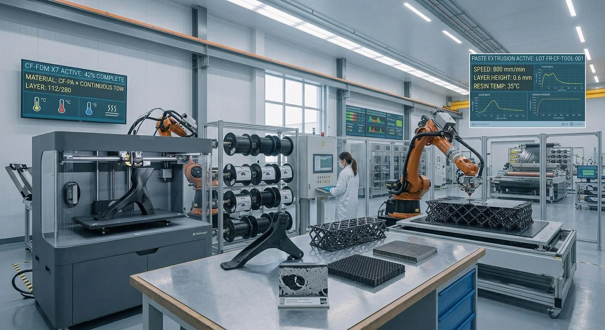
A technical comparison of paste extrusion and filament deposition (FDM/FFF) methods for continuous carbon fiber 3D printing, covering process fundamentals, mechanical properties, cost analysis, material systems, and application suitability for production-grade composite parts.
Additive manufacturing with continuous carbon fiber reinforcement has transitioned from research curiosity to production-ready technology over the past five years. Unlike short-fiber-filled filaments (which provide only modest reinforcement), continuous fiber 3D printing embeds unbroken carbon fiber tows throughout a thermoplastic or thermoset matrix, achieving fiber volume fractions of 35–55% and mechanical properties approaching those of traditional prepregged laminates. Two distinct process families have emerged: filament deposition (also called fused filament fabrication, FFF, or CF-FDM) which uses a continuous fiber-reinforced filament fed through a heated nozzle; and paste extrusion (also known as direct ink writing, DIW, or continuous fiber extrusion), where a carbon fiber tow is impregnated in-situ with a liquid thermoset or thermoplastic paste and deposited through a nozzle. The global market for continuous fiber 3D printing reached $385 million in 2025 (SmarTech Publishing), with compound annual growth projected at 28.4% through 2032, driven primarily by tooling, jigs and fixtures, and end-use structural brackets in aerospace and automotive applications.
Process Fundamentals: Filament Deposition vs Paste Extrusion
| Parameter | Filament Deposition (CF-FDM) | Paste Extrusion (DIW) |
|---|---|---|
| Feedstock form | Pre-impregnated continuous fiber filament (1.75–2.85 mm diameter) | Separate dry fiber tow + liquid resin (epoxy, acrylic, or PEKK paste) |
| Matrix material | Thermoplastic (PA, PEKK, PEEK, PC) | Thermoset (epoxy, acrylic) or thermoplastic paste |
| Fiber volume fraction (Vf) | 35–50% | 40–58% |
| Printing temperature | 260–400°C (nozzle), depending on matrix | Room temp to 80°C (material-dependent) |
| Layer height (typical) | 0.15–0.40 mm | 0.20–0.80 mm |
| Print speed (typical) | 100–800 mm/min (CF-reinforced) | 200–2000 mm/min |
| Typical void content | 2–8% | 0.5–3% |
| Post-processing | None or annealing (90–130°C for PA) | Oven cure (80–150°C, 2–8 hours) for thermoset |
| Layer adhesion | Thermal fusion between layers | Chemical crosslinking (thermoset) or solvent (paste) |
| Build volume (commercial systems) | Up to 600 × 400 × 300 mm (desktop); 1000 × 800 × 600 mm (industrial) | Up to 2000 × 1000 × 800 mm (robotic arm extrusion) |
| Representative systems | Markforged X7, Anisoprint Composer, Desktop Metal Fiber | CEAD Flexbot, Cincinnati BAAM, Ingersoll MasterPrint |
| System cost (complete) | $50,000–150,000 | $200,000–1,200,000 |
Mechanical Property Comparison
The mechanical performance of continuous fiber 3D-printed parts is governed by three factors: fiber volume fraction, void content, and interlayer bond strength. Paste extrusion systems currently achieve higher fiber volume fractions (up to 58% vs 50% for filament) and significantly lower void content (0.5–3% vs 2–8%), giving them an inherent mechanical advantage. However, filament-deposited parts benefit from the high-temperature performance of thermoplastic matrices (PEEK: Tg 143°C, continuous service to 260°C) which paste-extruded thermoset systems cannot match (epoxy: Tg 100–180°C, continuous service 80–160°C).
| Property | CF-FDM (PA+CF, Vf 45%) | Paste Extrusion (Epoxy+CF, Vf 52%) | Paste Extrusion (PEKK+CF, Vf 48%) | Reference: Aerospace Prepreg Laminate (Vf 60%) |
|---|---|---|---|---|
| Tensile strength (MPa) | 400–700 | 700–950 | 600–850 | 1,200–2,200 |
| Tensile modulus (GPa) | 40–60 | 65–85 | 55–75 | 100–140 |
| Flexural strength (MPa) | 280–480 | 550–780 | 450–650 | 900–1,500 |
| Interlaminar shear strength (MPa) | 8–18 | 25–40 | 18–30 | 45–70 |
| Compression strength (MPa) | 200–350 | 380–530 | 320–450 | 600–1,000 |
| Density (g/cm³) | 1.30–1.45 | 1.45–1.60 | 1.40–1.55 | 1.55–1.65 |
| Heat deflection temp (HDT, 1.82 MPa) | 120–155°C | 100–180°C | 130–170°C | 180–250°C |
| Void content | 3–7% | 0.8–2.5% | 1.5–3.5% | <1% |
| Z-axis strength (relative to X-Y) | 15–30% | 40–55% | 30–45% | 85–95% (quasi-isotropic) |
Material System Comparison
- Filament CF-PA (polyamide): Most widely used continuous fiber filament. Good impact resistance (Izod 80–120 J/m), moisture absorption 2.8% (24h saturation), cost $250–500/kg for CF-reinforced filament. Suitable for tooling, jigs, and prototyping.
- Filament CF-PEEK (polyetheretherketone): High-temperature aerospace grade. Continuous service temperature 260°C, chemical resistance superior to PA. Cost $800–1,500/kg. Used for flight-weight brackets, ducting, and high-temperature tooling.
- Filament CF-PEKK: Alternative to PEEK with lower processing temperature (340–370°C vs 370–400°C). Better interlayer adhesion than PEEK. Cost $600–1,200/kg.
- Paste epoxy + CF: Lowest void content among 3D-printed CF composites (0.8–2.5%). Requires oven cure post-process. Cost (resin): $50–120/kg. Dry fiber tow: $30–60/kg. Total material cost per kg of printed part: $120–200.
- Paste acrylic + CF: UV-curable, no oven required. Faster cycle times but lower temperature performance (HDT 60–90°C). Used for large-scale tooling and patterns. Cost: $80–150/kg.
- Paste PEKK + CF: Combines the layup quality of paste extrusion with high-temperature thermoplastic matrix. Requires heated deposition head (120–160°C). Cost: $500–900/kg.
Cost Analysis: Per-Part Comparison
For a representative part — a 300 mm × 150 mm × 25 mm structural bracket weighing 180 g in its final composite form — the following cost comparison applies at production volumes of 100, 1,000, and 10,000 parts per year.
| Cost Element | CF-FDM (PA+CF) | Paste Extrusion (Epoxy+CF) | Traditional Compression Molded Prepreg |
|---|---|---|---|
| Tooling / mold cost | $0 (no mold) | $0 (no mold) | $8,000–18,000 (steel mold) |
| Material cost per part | $28–52 | $22–36 | $18–30 |
| Print time per part | 4.5–8 hours | 2.5–5 hours | 0.5–1 hour (cure cycle) |
| Labor per part (post-processing) | $8–12 (support removal, sanding) | $15–25 (oven cure, surface finishing) | $5–10 (trimming, inspection) |
| Total cost per part (100 pcs/year) | $45–78 | $42–68 | $280–520 (incl. tooling amortization) |
| Total cost per part (1,000 pcs/year) | $38–58 | $34–48 | $38–65 (tooling amortized) |
| Total cost per part (10,000 pcs/year) | $35–52* | $30–42* | $22–38 |
*At 10,000 parts/year, CF-FDM and paste extrusion require multiple printer units (3–8 machines) or larger industrial systems, increasing capital cost. Traditional molding benefits from fully amortized tooling and sub-5-minute cycle times.
Application Suitability by Industry
- Aerospace tooling (cure fixtures, drill jigs): Both methods applicable. Paste extrusion preferred for large (1–2 m) fixtures due to larger build volume and lower void content ensuring thermal stability through autoclave cycles at 180°C.
- Automotive structural brackets and prototypes: CF-FDM is cost-effective for low-volume (under 5,000 parts/year) brackets and prototypes. Paste extrusion selected when mechanical properties equivalent to woven CFRP are required.
- Marine and offshore components: Paste extrusion with epoxy matrix is preferred for its lower water absorption (0.3–0.8% vs 1.5–3.0% for PA-based CF-FDM).
- Large-format tooling for wind energy: Paste extrusion dominates — robotic arm systems can print continuous CF structures up to 8 meters in length for blade mold tooling and mandrels.
- Medical and prosthetics: CF-FDM with PA or PEKK matrix is preferred for patient-specific orthoses and prosthetic components due to lower system cost and established biocompatibility pathways.
Process Limitations and Design Rules
Filament Deposition Limitations: Continuous fiber filament deposition has fundamental geometric constraints. The filament cannot be cut mid-print (most systems), meaning each continuous fiber path must be carefully routed within the layer. Overhangs require soluble supports. Minimum internal radius is 3–5 mm for CF-reinforced filament (vs 1–2 mm for unreinforced). Fiber steering is limited to 15–25° curvature change per layer before tow buckling occurs. The interlayer bond in CF-FDM is predominantly thermal — Z-strength is typically 15–30% of X-Y strength, making parts inherently orthotropic.
Paste Extrusion Limitations: Paste-extruded thermoset parts require a post-cure oven cycle (2–8 hours at 80–150°C), adding to cycle time and requiring oven capital investment ($15,000–60,000 for production-capable ovens). The liquid resin system creates a messier process environment and requires ventilation for volatile organic compounds (VOCs). Fiber placement accuracy is lower than filament deposition (±0.5 mm vs ±0.2 mm for filament) due to the semi-liquid bead spreading under nozzle pressure.
FAQ: Continuous Fiber 3D Printing
Q: Can continuous fiber 3D printing replace traditional composite manufacturing (prepreg layup, RTM)?
For production volumes under 1,000–5,000 parts per year, continuous fiber 3D printing offers a compelling alternative — particularly for tooling, jigs, fixtures, and custom/low-volume brackets. At these volumes, the elimination of mold cost (typically $8,000–50,000 for composite tooling) and reduced labor (no manual ply cutting, layup, or bagging) offset the slower cycle times. However, for high-volume production (10,000+ parts/year), traditional compression molding or automated tape laying (ATL) remains more economical. The mechanical properties of 3D-printed continuous fiber composites currently reach 50–70% of aerospace-grade prepreg laminates — sufficient for tooling and secondary structures, but below requirements for primary flight structures. Expect this gap to narrow as fiber volume fractions improve (target: 60% Vf by 2028, per Oak Ridge National Laboratory roadmap).
Q: Which 3D printing method produces better surface finish — filament deposition or paste extrusion?
Filament deposition generally produces better as-printed surface finish (Ra 3–8 μm vs Ra 8–20 μm for paste extrusion) because the solid filament maintains its cross-section through the nozzle and produces consistent bead geometry. Paste extrusion's semi-liquid bead can sag or spread on horizontal surfaces, especially at layer heights above 0.5 mm, and typically requires post-processing sanding or a gel-coat for cosmetic applications. However, paste extrusion using UV-curable acrylic resins achieves improved surface quality (Ra 5–12 μm) by rapidly gelling the deposited bead after extrusion, though the surface is still inferior to filament deposition. For visible carbon fiber aesthetic parts, CF-FDM followed by vapor smoothing (for PA) is the preferred approach.
Q: What are the key barriers to wider adoption of continuous fiber 3D printing in production?
Four barriers remain. First, print speed — even at 1,000 mm/min, producing a large structural part takes 6–24 hours. High-speed deposition head research aims for 5,000–10,000 mm/min by 2028. Second, certification — aerospace and automotive OEMs require process qualification data that does not yet exist for continuous fiber 3D printing at scale. The FAA has approved Markforged parts for non-structural cabin applications only (as of 2025). Third, fiber steering limitations — current systems cannot lay fibers along truly curved load paths with variable tow width (unlike AFP), limiting design optimization. Fourth, cost of high-temperature thermoplastic filaments (CF-PEEK at $800–1,500/kg) remains prohibitive for cost-sensitive applications. Paste extrusion addresses some of these barriers (lower material cost, larger build volume) but introduces post-cure cycle and surface quality trade-offs. The consensus from the 2025 SAMPE and CompositesWorld industry surveys is that continuous fiber AM will first achieve production maturity in large-format tooling (wind, marine) and aerospace non-structural parts within 3–5 years.
Part of topic
Related Articles
- Bio-Based Carbon Fiber Precursors: Lignin and Polyethylene for Low-Cost Production
- Large-Tow Carbon Fiber Cost Analysis: 48K vs 60K Price-Performance Comparison
- Carbon Fiber-Resin Interface Bonding: Surface Treatment and Coupling Agent Optimization
- Digital Twin for Carbon Fiber Manufacturing: Real-Time Process Monitoring and Defect Prevention
- Thermoplastic Carbon Fiber Welding for Automotive: Ultrasonic and Induction Welding Process Windows
- Large-Tow Carbon Fiber Wet Spinning: Process Optimization for 48K/60K Production Efficiency
Interested in Our Products?
Contact our team for competitive pricing and technical specifications.
Get a QuoteRelated Products

Carbon fiber standard plate-3k stripe
Lightweight, ultra-rigid standard sheets for drone fuselages, robot housings, facades and structural applications.

Carbon Fiber Plate — 3K Twill T700 1.5mm
Thin 1.5mm carbon fiber plate with 3K twill weave surface. Lightweight and stiff, commonly used for covers, panels, drone bodies, and applications requiring a premium aesthetic appearance.

Square Carbon Fiber Tube — 3K Twill T700
Square cross-section carbon fiber tube manufactured with 3K twill weave for torsional strength. Preferred for structural frames, trusses, and support columns where rectangular geometry offers design flexibility.

Carbon Fiber Plate — 3K Twill T700 3.0mm
Medium-thickness 3.0mm carbon fiber plate offering significantly higher load capacity while maintaining attractive 3K twill finish. Suitable for structural brackets, reinforcement plates, and load-bearing panels.

Carbon Fiber Plate — UD Unidirectional T700
Unidirectional carbon fiber plate with all fibers oriented in a single direction for maximum strength along the fiber axis. Essential for structural reinforcements, splints, and applications where load direction is predictable.