
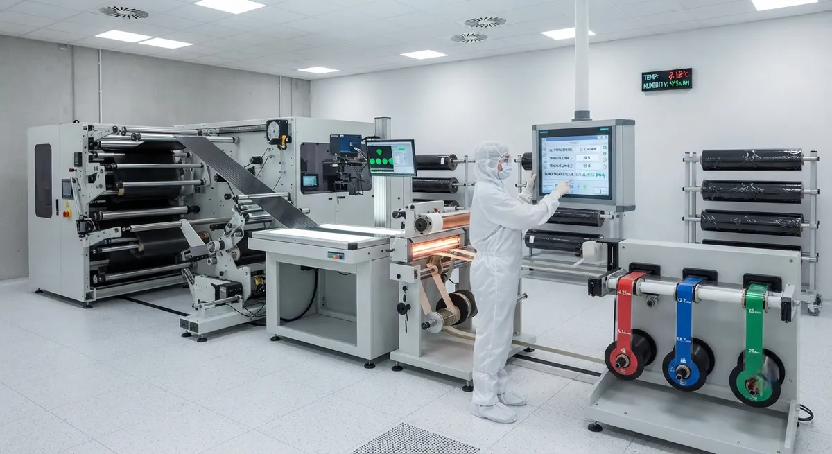
Technical guide to carbon fiber prepreg slitting and joining processes for wide-width processing. Learn about slitting tolerances, splice joint strength, automated tape laying integration, and quality control parameters.
Introduction to Wide-Width Prepreg Processing
The aerospace and automotive composites industries increasingly demand wider carbon fiber prepreg formats to maximize the throughput of automated fiber placement (AFP) and automated tape laying (ATL) systems. Standard prepreg roll widths of 300-600 mm are often insufficient for large structural components such as wing skins (12-18 m length), fuselage barrels (3-5 m diameter), or automotive floor panels (1.5-2.0 m width). Wide-width prepreg processing — encompassing slitting of master rolls into narrower tapes and in-line joining of multiple tape widths into wider formats — has become a critical enabler for high-rate composite manufacturing. This article provides a comprehensive technical overview of prepreg slitting and joining technologies, quality parameters, and integration with automated layup equipment.
Prepreg Slitting: Process Parameters and Quality Control
Prepreg slitting converts master rolls (typically 1,000-1,500 mm width) into narrower tape widths ranging from 6.35 mm (1/4-inch AFP tow) to 300 mm (12-inch ATL tape). The slitting process must maintain precise width tolerances and clean edge quality to prevent AFP/ATL machine misfeeds and tow twist defects. Modern servo-driven slitting systems achieve width tolerances of ±0.125 mm for AFP tow widths (6.35-12.70 mm) and ±0.25 mm for ATL tape widths (75-300 mm), with blade life extending to 15,000-25,000 linear meters between changes when using tungsten carbide blades with 0.5-1.0 micron edge radii. The following table summarizes critical slitting parameters for different prepreg material forms:
| Parameter | AFP Tow (6.35-12.7 mm) | Narrow ATL Tape (25-75 mm) | Wide ATL Tape (150-300 mm) | Unidirectional Fabric (300-600 mm) |
|---|---|---|---|---|
| Width Tolerance (mm) | ±0.125 | ±0.175 | ±0.250 | ±0.500 |
| Slitting Speed (m/min) | 15-30 | 20-40 | 10-25 | 8-20 |
| Blade Type | Rotary shear | Rotary shear | Crush cut | Ultrasonic |
| Edge Fuzz Rating (max) | Class A (0.05 mm) | Class A (0.05 mm) | Class B (0.10 mm) | Class B (0.10 mm) |
| Tension Control (N/cm width) | 0.5-1.5 | 1.0-2.5 | 2.0-4.0 | 3.0-6.0 |
| Web Guiding Accuracy (mm) | ±0.25 | ±0.50 | ±0.75 | ±1.00 |
| Waste Factor (%) | 1.5-3.0 | 1.0-2.0 | 0.5-1.5 | 0.5-1.0 |
| Inspection Frequency | 100% vision | 100% vision | Sampled (1/m) | Sampled (1/3m) |
Prepreg Joining Technologies for Wide-Width Formats
Joining multiple prepreg widths into wider formats enables ATL systems to deposit material at rates exceeding 50-80 kg/hour, compared to 15-30 kg/hour with standard-width tapes. Three primary joining technologies have been developed for carbon fiber prepreg:
- Hot-melt edge bonding: A thermoplastic interlayer film (typically polyamide 6/6, polyetherimide, or polyetheretherketone) is applied at the abutting edges of adjacent prepreg tapes, followed by localized heating to 220-280°C under 50-150 kPa pressure. Peel strengths of 2.5-5.0 N/mm are achieved with polyetherimide films, with the joint zone occupying 8-12 mm width. This method is preferred for thermoset prepregs (epoxy, BMI, cyanate ester) where the joint must survive AFP/ATL payoff without delamination.
- Ultrasonic spot welding: Concentrated ultrasonic energy (20-40 kHz, 500-2000 W) is applied through a sonotrode to fuse the prepreg edges through localized matrix melting. Weld spots of 5-8 mm diameter are spaced at 15-25 mm intervals along the splice line. This process achieves joint efficiencies of 75-90% in tensile mode with no added material, though cyclic fatigue performance under AFP steering loads requires careful optimization of weld density.
- Pressure-sensitive adhesive (PSA) tape splicing: A thin (0.025-0.075 mm) acrylic or silicone PSA transfer tape is applied to the prepreg backing paper, creating a continuous bond across the tape width. Peel adhesion of 8-15 N/25mm at the prepreg-backing interface allows the splice to survive unwind and payoff but separates cleanly during AFP deposition without contaminating the compaction roller. This is the most cost-effective method at $0.15-0.30 per splice meter but has the lowest peel strength at elevated temperatures above 50°C.
Splice Joint Mechanical Performance
The mechanical integrity of prepreg splices directly impacts AFP/ATL process reliability. Splice failures during automated layup cause machine stoppages, material waste, and in extreme cases, damage to the layup head. A comprehensive study of splice performance under AFP process conditions yields the following data:
| Joining Method | Peel Strength (N/mm) | Max. AFP Speed Before Failure (m/min) | Min. Bend Radius (mm) | Temperature Limit (°C) |
|---|---|---|---|---|
| Hot-melt (PA66 interlayer) | 4.2 | 85 | 15 | 180 |
| Hot-melt (PEI interlayer) | 3.8 | 75 | 20 | 210 |
| Ultrasonic spot weld | 2.1 | 55 | 25 | 120 |
| PSA transfer tape | 1.5 | 40 | 10 | 50 |
Integration with AFP and ATL Systems
Wide-width prepreg formats produced by slitting and joining must be compatible with the material handling systems of AFP and ATL equipment. Key integration parameters include: payout tension uniformity across the full width (target: ±10% variation), splice thickness buildup (should not exceed 125% of nominal prepreg thickness), and splice spacing (typically 3-5 splices per 100 m of prepreg for hot-melt joining, versus 8-12 per 100 m for PSA splicing). The leading AFP machine manufacturers — including Electroimpact, Coriolis Composites, and MTorres — have published material specification requirements for wide-width prepreg formats under SAE AMS 3892/1 and Airbus AIPS 02-03-045 standards, which specify a maximum allowable splice gap of 0.50 mm and a splice overlap of zero (butt joint configuration).
Quality Assurance and Non-Destructive Testing
Quality assurance for prepreg slitting and joining operations employs a combination of in-line and off-line inspection methods. In-line systems using line-scan cameras (2K-8K pixel resolution, 10-40 kHz line rate) detect edge defects, width deviations, and splice gaps in real time at processing speeds up to 40 m/min. Laser profilometry (30-100 µm Z-axis resolution) monitors splice thickness buildup and edge crown. Off-line quality checks include peel testing per ASTM D1876 (T-peel at 50 mm/min), microscopy of cross-sectioned splices for void content (<2% target), and thermal analysis (DSC per ASTM E1269) to verify that the joining process has not degraded prepreg cure kinetics. Statistical process control data from a high-volume prepreg slitting facility indicates a first-pass yield of 96.8% for AFP tow slitting and 93.5% for wide-width ATL tape joining, with the primary defect modes being edge fuzz (52% of rejects) and splice gap non-conformance (28% of rejects).
Frequently Asked Questions
What is the maximum practical width for joined carbon fiber prepreg?
The maximum practical joined prepreg width for ATL systems is currently 1,500 mm (60 inches), limited by the width of the compaction roller and the steering kinematics of the ATL head. Wider formats up to 2,000 mm have been demonstrated in laboratory settings using dual-roller compaction systems, but production adoption remains limited due to ply steering challenges at widths exceeding 1,500 mm. AFP systems typically use individual tow widths of 6.35-12.70 mm and do not require joined prepreg formats, instead relying on multiple tow payout from creel systems with up to 32 independent tows.
How does prepreg slitting affect the mechanical properties of the final cured composite?
Properly controlled slitting with sharp blades (edge radius <1.0 micron) and clean edge quality produces no measurable degradation in cured laminate mechanical properties. Studies comparing laminates from slit-edge prepreg versus as-manufactured prepreg show tensile strength within ±2%, compressive strength within ±3%, and interlaminar shear strength within ±2% of control specimens. However, excessively dull blades causing edge fuzz or fiber fraying can reduce fatigue life by 15-25% under cyclic loading due to crack initiation at damaged fiber ends. Regular blade condition monitoring with optical edge inspection is essential.
Can different prepreg material systems be joined together for hybrid laminates?
Dissimilar prepreg joining is feasible but requires careful matching of resin system cure chemistry. Epoxy- epoxy splices with compatible curing schedules (similar cure temperatures within ±15°C and similar cure speeds) can be joined using hot-melt methods with a compatible interlayer film. However, joining epoxy to BMI or epoxy to cyanate ester prepregs requires a graded interlayer approach where a thin (0.05-0.10 mm) film of intermediate chemistry bridges the two systems. Without proper interlayer design, the joint interface becomes a weak zone with 35-55% reduction in interlaminar shear strength.
What is the shelf life of slit and joined prepreg compared to standard prepreg rolls?
Slit and joined prepreg maintains the same out-life and shelf-life characteristics as the original master roll material, provided the joining process does not expose the material to temperatures exceeding 40°C for extended periods. Standard epoxy prepreg (350°F cure) has a typical out-life of 10-15 days at 21°C and a shelf life of 12 months at -18°C. Hot-melt joining processes that locally heat the prepreg to 220-280°C for less than 2 seconds do not measurably advance the resin cure state (DSC analysis shows <0.5% cure advancement, below the typical measurement noise of 1.5%).
How does joined prepreg perform in AFP steering applications?
Joined prepreg for AFP steering applications (curved tow paths with radii of 500-3,000 mm) requires splice joints oriented perpendicular to the tow direction, with maximum splice spacing of 3-5 meters between joints for 6.35 mm tow. Hot-melt joined prepreg with PA66 interlayer achieves a steering success rate of 98.5% at 1,200 mm steering radius and 45 m/min layup speed, compared to 99.8% for continuous (unspliced) prepreg. PSA-joined prepreg is not recommended for steering radii below 2,000 mm as splice separation occurs in 12-18% of steering events at 1,500 mm radius.
Part of topic
Related Articles
- Bio-Based Carbon Fiber Precursors: Lignin and Polyethylene for Low-Cost Production
- Large-Tow Carbon Fiber Cost Analysis: 48K vs 60K Price-Performance Comparison
- Carbon Fiber-Resin Interface Bonding: Surface Treatment and Coupling Agent Optimization
- Digital Twin for Carbon Fiber Manufacturing: Real-Time Process Monitoring and Defect Prevention
- Thermoplastic Carbon Fiber Welding for Automotive: Ultrasonic and Induction Welding Process Windows
- Large-Tow Carbon Fiber Wet Spinning: Process Optimization for 48K/60K Production Efficiency
Interested in Our Products?
Contact our team for competitive pricing and technical specifications.
Get a QuoteRelated Products

Carbon fiber standard plate-3k stripe
Lightweight, ultra-rigid standard sheets for drone fuselages, robot housings, facades and structural applications.

Carbon Fiber Plate — 3K Twill T700 3.0mm
Medium-thickness 3.0mm carbon fiber plate offering significantly higher load capacity while maintaining attractive 3K twill finish. Suitable for structural brackets, reinforcement plates, and load-bearing panels.

Carbon Fiber Plate — 3K Twill T700 1.5mm
Thin 1.5mm carbon fiber plate with 3K twill weave surface. Lightweight and stiff, commonly used for covers, panels, drone bodies, and applications requiring a premium aesthetic appearance.

Custom Carbon Fiber Medical Device Components
Medical-grade carbon fiber components manufactured for imaging equipment, surgical instruments, and patient support systems. Carbon fiber's radiolucency (X-ray transparency) and high strength-to-weight ratio make it ideal for CT scanner beds, wheelchair frames, surgical robot arms, and MRI-compatible accessories. Biocompatible resin systems available.

Square Carbon Fiber Tube — 3K Twill T700
Square cross-section carbon fiber tube manufactured with 3K twill weave for torsional strength. Preferred for structural frames, trusses, and support columns where rectangular geometry offers design flexibility.