
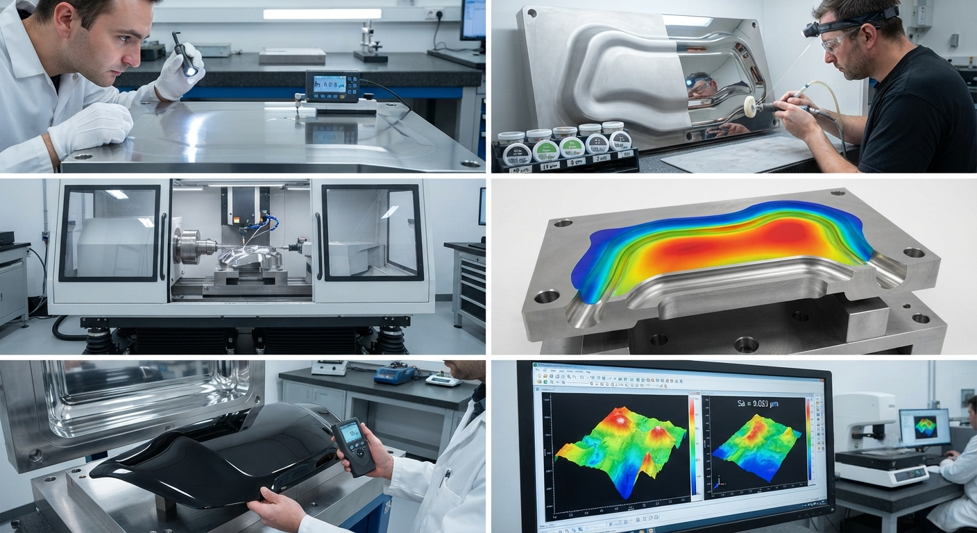
B2B technical guide to optical-grade tooling for carbon fiber precision molding. Covers tool material selection (invars, stainless steel, nickel-shell), surface finishing processes (diamond polishing, EDM, laser texturing), thermal management for dimensional stability, CTE compensation, vacuum integrity, tool certification protocols, and surface replication fidelity. Includes comparative data on surface roughness, tool life, and cost across five tool material systems.
Introduction to Optical-Grade Tooling for Carbon Fiber Molding
Optical-grade tooling — mould surfaces finished to sub-micron roughness (Ra < 0.1 µm) with dimensional accuracy within ± 0.05 mm over the entire tool surface — is the enabling technology for precision carbon fiber composite components that require Class A surface finish, tight geometric tolerances, or both. Applications demanding optical-grade tooling span across aerospace (radomes, cockpit transparencies, interior trim panels), automotive (exterior body panels, headlamp housings, decorative trim), consumer electronics (smartphone cases, laptop housings, drone frames), and medical devices (MRI-compatible housings, surgical instrument components). The surface quality of the molded CFRP part is a direct replica of the tool surface quality — every scratch, pit, polished-grain boundary, and surface waviness feature on the tool surface is transferred to the molded part with a replication fidelity typically exceeding 95% for standard prepreg compression molding and 98% for film-assisted RTM processes.
The global market for precision composite tooling was estimated at $840 million in 2025, with optical-grade tooling representing approximately 22% of this value. The increasing adoption of carbon fiber in visible, cosmetic, and aerodynamically-critical applications is driving demand for tooling with surface finishes of Ra < 0.05 µm — approaching the surface quality of polished glass or optical lenses. This article presents a comprehensive technical overview of optical-grade tooling for carbon fiber precision molding, covering material selection, surface finishing, thermal management, certification, and process optimisation across five tool material systems.
Tool Material Systems for Optical-Grade Surface Finish
The selection of tool material is the foundational decision determining achievable surface finish, dimensional stability, tool life, and cost. Five material systems are evaluated for optical-grade CFRP molding applications:
| Tool Material | Achievable Ra (µm) | Max Service Temp (°C) | CTE (µm/m·°C) | Thermal Conductivity (W/m·K) | Tool Life (cycles) | Relative Cost Index | Best Applications |
|---|---|---|---|---|---|---|---|
| Invar 36 (Fe-36Ni) | 0.01–0.03 | 400 | 1.2–1.5 | 10–13 | 10,000+ | 5.0–8.0 | Aerospace Class A, autoclave-cured prepreg, large panels |
| Maraging steel (C350/C250) | 0.02–0.05 | 500 | 10–12 | 20–30 | 50,000+ | 3.0–5.0 | High-volume compression molding, SMC/BMC |
| Stainless steel 420 (pre-hardened) | 0.03–0.08 | 350 | 10.3–11.5 | 22–28 | 20,000+ | 1.0 (baseline) | General-purpose optical surfaces, interior trim |
| Electroformed nickel (Nickel-shell) | 0.005–0.02 | 250 | 13–14 | 70–90 | 500–5,000 | 4.0–7.0 | Complex geometry, rapid heat-up, prototype to mid-volume |
| Aluminium 7075-T6 (hard anodized) | 0.05–0.15 | 200 | 23.6 | 130–170 | 2,000–8,000 | 0.6–0.8 | Prototype, Class B surfaces, low-temperature cure (≤ 180°C) |
Surface Finishing Processes for Optical-Grade Tools
Achieving optical-grade surface finish on composite moulds requires a multi-stage finishing process, regardless of the tool material. The general sequence includes rough machining, semi-finish machining, heat treatment (stress relief), finish machining, and surface finishing. The following processes are specific to the final surface quality:
- Diamond mechanical polishing: The standard process for achieving Ra < 0.1 µm on ferrous tool materials (steel, maraging steel, Invar). The sequence progresses through diamond suspension grit sizes: 45 µm (rough polish) → 15 µm (semi-finish) → 6 µm (fine polish) → 3 µm (super-finish) → 1 µm (optical finish). Each stage requires 30–90 minutes of polishing time per 0.1 m² of tool surface, with a total polisher time of 8–40 hours for a typical automotive fascia tool (1–3 m² surface area). The polishing direction is rotated by 45–90° between grit stages to remove the previous stage's scratch pattern. Final inspection: no visible scratches under 5× magnification, surface roughness Ra < 0.05 µm by contact profilometer (2D, 5.6 mm cut-off length) or white-light interferometer (3D surface mapping).
- Diamond turning (single-point diamond turning — SPDT): Used for non-ferrous tool materials (electroformed nickel, aluminium, copper-beryllium) where a diamond tool can machine directly to Ra < 0.02 µm without subsequent polishing. SPDT on a ultra-precision lathe (air-bearing spindle, thermal-stabilised enclosure ± 0.01°C, vibration isolation < 0.1 µm amplitude) achieves form accuracy of ± 0.5 µm over a 300 mm diameter surface. Applications include moulds for CFRP optical components — reflectors, light guides, and windows — where the moulded part replicates the diamond-turned surface to within 0.05 µm Ra.
- EDM finishing (sinking EDM with fine electrode): For tool cavities with complex 3D surfaces, electrical discharge machining with fine-patterned graphite or copper electrodes achieves surface finishes of Ra 0.2–0.4 µm. Multi-stage EDM with decreasing discharge energy: rough (I = 10–20 A, Ra 3–6 µm) → semi-finish (I = 3–8 A, Ra 0.8–1.5 µm) → finish (I = 0.5–3 A, Ra 0.3–0.6 µm) → micro-finish (I < 0.5 A, Ra 0.1–0.25 µm). The EDM recast layer (white layer, 5–20 µm thick) must be removed by subsequent polishing or abrasive flow machining (AFM) for optical-grade surfaces, as the recast layer contains microcracks that would replicate to the molded part surface.
- Laser polishing (ultra-short pulse laser): An emerging non-contact finishing process using picosecond or femtosecond pulsed lasers (1–50 ps pulse duration, 10–500 kHz repetition rate, 5–50 W average power) to ablate surface asperities without thermal damage to the substrate. Laser polishing of steel and Invar tools achieves Ra improvement from 0.3–0.5 µm (machined finish) to 0.05–0.15 µm in 15–30 minutes per 0.1 m². While laser polishing is not yet a replacement for diamond polishing at the highest Ra levels (< 0.03 µm), it offers advantages for selective-area polishing (localised tool features, hard-to-reach corners) and for finishing tools with integrated conformal cooling channels where abrasive access is limited.
Thermal Management for Dimensional Stability
Optical-grade tooling demands exceptional thermal stability throughout the cure cycle, as tool temperature gradients cause differential expansion that directly translates into part dimensional variation. The thermal management strategy for precision CFRP tooling includes:
- Conformal cooling/heating channels: Conventionally machined straight-hole cooling channels produce temperature gradients of 5–15°C across the tool surface during a typical 120–180°C autoclave or hot-press cure cycle. Conformal channels — fabricated by laser powder bed fusion (LPBF) additive manufacturing for steel tools, or by brazed tube networks for nickel-shell tools — follow the tool surface contour at a constant standoff distance of 8–15 mm, achieving surface temperature uniformity of ± 1.5°C. For an Invar tool with LPBF conformal channels (maraging steel or Invar powder), thermal simulation (ANSYS or equivalent) predicts: heat-up rate 3–8°C/min (vs. 0.5–2°C/min for straight channels), cooldown rate 4–10°C/min (vs. 1–3°C/min), and maximum thermal gradient 2°C (vs. 12°C).
- CTE compensation in tool design: The mismatch between tool material CTE and CFRP part CTE (near-zero for carbon fiber in-plane, 30–60 ppm/°C through-thickness) must be compensated in the tool geometry design. For an Invar 36 tool (CTE 1.2–1.5 ppm/°C), the tool cavity dimensions are designed at room temperature (20°C) to produce the specified part dimensions at the cure temperature (typically 120–180°C). The compensation factor is calculated as: ΔL = L₀ × (α_tool — α_part) × (T_cure — 20). For a 500 mm part length cured at 150°C on an Invar tool, the compensation is: ΔL = 500 × (1.35 × 10⁻⁶ — 0.5 × 10⁻⁶) × (150 — 20) = 500 × 0.85 × 10⁻⁶ × 130 = 0.055 mm. For a stainless steel tool (CTE 11 × 10⁻⁶), the same calculation gives ΔL = 0.68 mm — over 12× larger, requiring significantly more precise CTE compensation and greater sensitivity to actual cure temperature variation.
- Active temperature control system: For autoclave-cured tools, an embedded thermocouple network (12–48 thermocouples per tool, located 3–5 mm below the tool surface) provides real-time temperature feedback for the cure controller. The controller uses PID or model-predictive control (MPC) to regulate autoclave air temperature, achieving a tool surface temperature ramp rate of 1–3°C/min with overshoot < 2°C and steady-state holding within ± 1°C of the set-point throughout the cure dwell.
Vacuum Integrity and Surface Quality
Vacuum integrity is a critical requirement for optical-grade composite molding, as vacuum leaks cause porosity in the molded part surface, degrading finish quality and potentially causing cosmetic rejection. The vacuum system for optical-grade tools must achieve and maintain:
- Tool leak rate: < 0.01 mbar·L/s per ISO 21359 (vacuum decay test, 5-minute hold at —0.95 bar). The tool vacuum seal is achieved by a perimeter O-ring groove (6 mm wide × 4 mm deep, corner radius 1.5 mm) machined into the tool flange, housing a silicone O-ring (30–50 Shore A, < 20% compression set) that seals against the vacuum bag or the mating tool half.
- Tool surface porosity: The tool material itself must be free of pinholes, micro-porosity, and inclusions down to the 0.05 mm scale. For electroformed nickel tools, the deposition process (nickel sulphamate bath, current density 2–5 A/dm², bath temperature 50–60°C, pH 3.5–4.5) must be controlled to produce a fully dense deposit (> 99.5% theoretical density) with no nodule formation or hydrogen pitting. For steel and Invar tools, the material must be certified as pinhole-free at 10× magnification on a 100 cm² representative area, with ultrasonic inspection (10 MHz, pulse-echo) scanning the entire tool surface at 1 mm resolution.
- Surface sealing treatment: Even pinhole-free tool materials benefit from a surface sealing treatment to prevent micro-crack wicking of volatiles during cure. For Ra < 0.05 µm optical surfaces, a 2–5 µm layer of amorphous diamond-like carbon (DLC) coating (deposited by PECVD at 200°C, hardness 15–25 GPa, coefficient of friction 0.05–0.15) provides both surface sealing and enhanced release characteristics. DLC-coated optical tools demonstrate a 5–8× reduction in mould release frequency (every 50–100 parts vs. every 10–20 parts for uncoated polished steel) and a 30–50% improvement in demolding force consistency.
Tool Certification and Surface Replication Verification
Before optical-grade tools are released for production, a structured certification protocol verifies that all surface and dimensional requirements are met:
- Surface roughness verification: Contact profilometer measurement per ISO 4287 (Ra, Rz, Rmax) at 12–24 locations distributed across the entire tool surface. Acceptance: Ra < 0.05 µm for Class A optical surfaces; Ra < 0.10 µm for Class B cosmetic surfaces. Areal surface roughness parameters (Sa, Sz per ISO 25178) are measured by white-light interferometry at three reference locations, providing 3D surface topography mapping over 5 mm × 5 mm areas. Additional acceptance criteria: Sa < 0.05 µm, no isolated peaks exceeding 0.3 µm height above the mean plane.
- Replication fidelity test: A test plaque is moulded using the standard process parameters (layup sequence, cure cycle, pressure). The moulded plaque surface roughness is measured at the same 12–24 locations as the tool surface. Replication fidelity is calculated as: R_fidelity = (1 — |Ra_part — Ra_tool| / Ra_tool) × 100%. Acceptance: R_fidelity ≥ 95% for optical-grade surfaces; R_fidelity ≥ 90% for cosmetic surfaces.
- Geometric dimension verification: Coordinate measuring machine (CMM) scan of the entire tool cavity surface at 0.5–2.0 mm point spacing. Surface deviation map (GD&T per ASME Y14.5-2009): profile tolerance ± 0.05 mm for optical-grade Class A tools; ± 0.10 mm for Class B tools. The CMM scan also verifies draft angles (target ± 0.2°), radius profiles (target ± 0.05 mm), and parting line flatness (target < 0.03 mm over 1 m).
- Thermal survey certification: A temperature mapping test under simulated cure conditions (vacuum bagged, thermocouple-equipped dummy part) documents the thermal uniformity of the tool surface. Acceptance criteria from the survey: all thermocouple readings within ± 2°C of set-point during the cure dwell phase; heat-up rate uniformity within ± 15% of the specified ramp rate; and no location exceeding the specified maximum temperature gradient of 3°C across the entire tool surface.
Frequently Asked Questions
What is the minimum tool surface roughness required to achieve a Class A carbon fiber part surface?
Class A surface finish for carbon fiber composite parts — defined as a surface with no visible fiber pattern (print-through), no porosity, and a smooth, glossy appearance suitable for direct painting without filler primer — typically requires a tool surface roughness of Ra ≤ 0.05 µm (preferred) to Ra ≤ 0.10 µm (minimum). However, roughness alone does not guarantee Class A finish; the following additional factors must be simultaneously controlled: (a) Tool surface waviness (low-frequency surface texture) must be < 0.5 µm over a 50 mm measurement length per ISO 4287 — waviness causes long-wavelength surface defects in the molded part that are visible even at low Ra values. (b) Resin shrinkage during cure — epoxy resins for CFRP typically shrink 0.5–2.0% by volume during cure, which can cause print-through of the fiber weave pattern (telegraphing). For Class A surfaces, low-shrink resin systems (shrinkage < 0.5%) are required, typically achieved by adding thermoplastic toughening agents (10–25% by weight in the resin formulation). (c) Fiber type and areal weight — a 200 g/m² or lighter plain-weave or satin-weave fabric on the tool-side surface layer minimises print-through compared to heavier 400–600 g/m² fabrics or unidirectional tapes. (d) Molding pressure — a minimum compaction pressure of 5–7 bar for compression molding or 6–8 bar absolute autoclave pressure ensures complete resin flow and consolidation. With all factors optimised, carbon fiber parts have been demonstrated with surface roughness Ra as low as 0.02–0.04 µm directly off the tool — equivalent to painted automotive body panel surfaces. At this level, the carbon fiber part can be painted with a single coat of clear coat (without primer) and meet OEM appearance standards.
How does tool material thermal expansion affect the dimensional accuracy of molded carbon fiber parts?
The coefficient of thermal expansion (CTE) mismatch between the tool material and the carbon fiber part is the most significant source of dimensional variation in precision CFRP molding. Carbon fiber laminates have a near-zero in-plane CTE (typically 0.5–2.0 ppm/°C for standard modulus fibers, 0.1–1.0 ppm/°C for high-modulus and ultra-high-modulus fibers) and a through-thickness CTE of 30–60 ppm/°C. The practical effect on part dimensions depends on tool material choice: Invar 36 (CTE 1.2–1.5 ppm/°C) provides the closest CTE match to carbon fiber, resulting in minimal dimensional change between cure temperature (120–180°C) and room temperature (20°C) — approximately 0.05–0.10 mm/m of part dimension. Stainless steel (CTE 10–12 ppm/°C) produces 0.6–0.9 mm/m dimensional change, requiring precise CTE compensation in tool design and tight control (± 3°C) of actual cure temperature. Aluminium (CTE 23–24 ppm/°C) produces dimensional changes of 1.5–2.2 mm/m, making it unsuitable for precision Class A tooling where dimensional tolerance < ± 0.1 mm is required. The practical implication for B2B buyers is critical: when procuring precision CFRP components, the tool material specification should be disclosed by the manufacturer, as it directly determines achievable dimensional tolerances. For components requiring tolerances of ± 0.05 mm/m or tighter, Invar 36 or electroformed nickel tooling is effectively mandatory. For ± 0.10–0.25 mm/m tolerances, stainless steel with documented CTE compensation is sufficient. For tolerances of ± 0.5 mm/m or looser, aluminium tools can be considered.
What is the typical lead time and cost for fabricating an optical-grade composite mold?
The lead time and cost for optical-grade composite tooling vary significantly with tool material, size, and complexity. For a benchmark tool of 0.5 m × 0.5 m (250 cm² projected area) for a Class A automotive interior trim part: Stainless steel 420 (baseline) — lead time 8–12 weeks, cost $25,000–$40,000. Invar 36 — lead time 12–20 weeks, cost $60,000–$100,000 (including Invar plate material cost of $120–$200/kg vs. $5–$15/kg for stainless steel). Electroformed nickel (nickel-shell) — lead time 8–14 weeks, cost $40,000–$80,000 (including mandrel fabrication, electroforming, and nickel-shell backup structure). Maraging steel — lead time 10–16 weeks, cost $35,000–$65,000 (material cost $30–$60/kg, requires post-machining heat treatment at 480–510°C for 3–6 hours to achieve 48–54 HRC hardness). For larger tools (1 m × 1 m projected area, typical for automotive exterior panels): tool costs scale by approximately 1.5–2.0× per 2× area increase (not linearly, because the surface finishing is the dominant cost, and finishing cost scales with surface area). The cost premium for optical-grade tooling (Ra < 0.05 µm) over standard finish tooling (Ra 0.2–0.4 µm) is approximately 40–80%, reflecting the additional 20–60 hours of diamond polishing and the more stringent surface inspection requirements. Tool maintenance cost should also be factored: optical-grade tools require surface reconditioning (re-polishing or DLC coating reapplication) every 2,000–10,000 cycles depending on the tool material and molding process, at a cost of 15–25% of the original tool cost. For Invar and DLC-coated steel tools, reconditioning frequency is at the higher end (5,000–10,000 cycles), while uncoated steel tools may require reconditioning every 2,000–5,000 cycles.
Part of topic
Related Articles
- Bio-Based Carbon Fiber Precursors: Lignin and Polyethylene for Low-Cost Production
- Large-Tow Carbon Fiber Cost Analysis: 48K vs 60K Price-Performance Comparison
- Carbon Fiber-Resin Interface Bonding: Surface Treatment and Coupling Agent Optimization
- Digital Twin for Carbon Fiber Manufacturing: Real-Time Process Monitoring and Defect Prevention
- Thermoplastic Carbon Fiber Welding for Automotive: Ultrasonic and Induction Welding Process Windows
- Large-Tow Carbon Fiber Wet Spinning: Process Optimization for 48K/60K Production Efficiency
Interested in Our Products?
Contact our team for competitive pricing and technical specifications.
Get a QuoteRelated Products

Custom Carbon Fiber Medical Device Components
Medical-grade carbon fiber components manufactured for imaging equipment, surgical instruments, and patient support systems. Carbon fiber's radiolucency (X-ray transparency) and high strength-to-weight ratio make it ideal for CT scanner beds, wheelchair frames, surgical robot arms, and MRI-compatible accessories. Biocompatible resin systems available.

Carbon fiber standard plate-3k stripe
Lightweight, ultra-rigid standard sheets for drone fuselages, robot housings, facades and structural applications.

Square Carbon Fiber Tube — 3K Twill T700
Square cross-section carbon fiber tube manufactured with 3K twill weave for torsional strength. Preferred for structural frames, trusses, and support columns where rectangular geometry offers design flexibility.

Carbon Fiber Plate — 3K Twill T700 3.0mm
Medium-thickness 3.0mm carbon fiber plate offering significantly higher load capacity while maintaining attractive 3K twill finish. Suitable for structural brackets, reinforcement plates, and load-bearing panels.

Carbon Fiber Plate — 3K Twill T700 1.5mm
Thin 1.5mm carbon fiber plate with 3K twill weave surface. Lightweight and stiff, commonly used for covers, panels, drone bodies, and applications requiring a premium aesthetic appearance.