
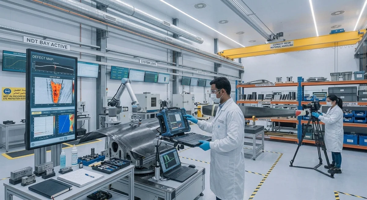
Non-destructive testing (NDT) is essential for quality assurance in carbon fiber composite manufacturing. This article compares ultrasonic testing, infrared thermography, and shearography for detecting delaminations, disbonds, porosity, and impact damage in CFRP components, with detection limits, cost data, and application guidance for B2B buyers.
Carbon fiber reinforced polymer (CFRP) composites are increasingly used in aerospace, automotive, wind energy, and sporting goods where structural integrity is critical. Unlike metals, where visual inspection often suffices, composite materials require sophisticated non-destructive testing (NDT) methods to detect internal defects that can compromise performance. The global composites NDT market is projected to reach $1.8 billion by 2030, driven by increasing CFRP adoption in safety-critical applications and regulatory requirements for manufacturing quality assurance.
The unique failure modes of composites — delamination, fiber breakage, matrix cracking, disbonding, and porosity — demand inspection techniques capable of detecting sub-surface anomalies in anisotropic, multi-layered material systems. Each NDT method offers different capabilities in terms of detection depth, resolution, scanning speed, and cost. Understanding these trade-offs is essential for B2B buyers selecting inspection equipment or contracting third-party NDT services.
Ultrasonic Testing (UT) for CFRP
Ultrasonic testing is the most widely used NDT method for carbon fiber composites, accounting for approximately 55-60% of all composite inspections globally. UT uses high-frequency sound waves (0.5-25 MHz) that propagate through the composite and reflect from interfaces, defects, and the back wall. Two primary configurations are used in production:
- Pulse-echo (reflection) mode: Single transducer sends and receives signals. Suitable for single-sided access. Detection depth: 0.5-50 mm. Resolution: detects defects as small as 1-3 mm at 5-10 MHz.
- Through-transmission mode: Separate transmitter and receiver on opposite sides. Higher sensitivity for porosity and disbonds. Requires dual-sided access. Best for thin laminates (1-15 mm).
- Phased array UT: Multiple piezoelectric elements (16-128) electronically steered to create cross-sectional images. Scanning speed: 5-20 m/h. Best inspection coverage and imaging capability.
- Air-coupled UT: No couplant required. Coupling through air gap of 5-30 mm. Reduced sensitivity but suitable for porous materials and in-process inspection.
| UT Method | Frequency Range | Min. Detectable Defect | Max Thickness | Scan Speed | Equipment Cost |
|---|---|---|---|---|---|
| Conventional pulse-echo | 2.25-10 MHz | 3 mm diameter | 50 mm | 2-5 m/h (manual) | $15,000-40,000 |
| Phased array UT | 1-15 MHz | 1 mm diameter | 80 mm | 10-30 m/h (automated) | $50,000-150,000 |
| Through-transmission UT | 0.5-5 MHz | 5 mm diameter | 30 mm | 3-8 m/h | $20,000-60,000 |
| Air-coupled UT | 50-500 kHz | 5-10 mm diameter | 10 mm | 5-15 m/h | $40,000-100,000 |
| Laser-UT (laser generation) | 1-20 MHz | 2 mm diameter | 25 mm | 100-500 m/h | $200,000-500,000 |
Detection Capabilities for Common Composite Defects
Ultrasonic testing excels at detecting planar defects oriented parallel to the composite surface — precisely the orientation of the most critical composite defect type: delamination. Key detection capabilities include:
- Delaminations: Readily detectable when oriented parallel to the surface. Minimum detectable size: 3-10 mm diameter depending on depth and frequency. Detection limit improves with higher frequency but at the cost of penetration depth.
- Porosity: Detectable as attenuation of the back-wall echo. 1-2% porosity by volume is typically detectable. Quantification requires reference standards and calibration.
- Disbonds: Between composite and core (honeycomb or foam) or between composite and metal inserts. Detection depends on acoustic impedance mismatch and bond line thickness.
- Impact damage: Barely visible impact damage (BVID) from 5-15 J impacts is detectable as delamination clusters. Detection rate: >90% for 10 J impacts in 3-5 mm laminates.
- Fiber waviness: Often visible in C-scan as variations in signal amplitude. Quantification requires specialized analysis techniques.
Infrared Thermography
Infrared thermography is a full-field, non-contact NDT technique that uses thermal imaging to detect subsurface defects. The composite surface is heated (by flash lamps, hot air, or induction), and an IR camera (typically 3-5 μm or 7-14 μm wavelength) records the cooling rate. Defects such as delaminations, disbonds, and moisture ingress appear as hot spots because they impede heat flow through the material.
- Pulsed thermography (flash thermography): High-energy xenon flash lamps (4-12 kJ) heat the surface in 2-10 ms. Best for thin laminates (1-5 mm). Detection depth limit: approximately 3-4 mm in CFRP. Equipment cost: $40,000-120,000.
- Lock-in thermography: Modulated heating (0.01-1 Hz) with phase-sensitive detection. Deeper penetration (5-8 mm) but slower. Superior signal-to-noise ratio. Equipment cost: $60,000-180,000.
- Induction thermography: Eddy current heating of carbon fibers (which are electrically conductive). Selective heating of fibers near defects. Best for detecting fiber orientation anomalies and impact damage.
| Parameter | Pulsed Thermography | Lock-in Thermography | Induction Thermography |
|---|---|---|---|
| Detection depth in CFRP | 2-4 mm | 4-8 mm | 3-6 mm |
| Min. detectable defect | 2-5 mm | 1-3 mm | 3-8 mm |
| Inspection area per shot | 0.1-0.5 m² | 0.05-0.2 m² | 0.05-0.3 m² |
| Inspection time per area | 5-30 seconds | 30-300 seconds | 5-30 seconds |
| Suitable for thick laminate (>10 mm) | Limited | Moderate | Limited |
| Suitable for thin skin-core structures | Excellent | Good | Good |
| Equipment cost range | $40K-120K | $60K-180K | $80K-200K |
Shearography (Speckle Pattern Shearing Interferometry)
Shearography is an optical NDT technique that measures out-of-plane surface deformation gradients under applied stress (thermal, vacuum, pressure, or vibration). It is particularly well-suited for detecting disbonds and delaminations in sandwich structures and bonded composite assemblies. The technique creates a speckle pattern image of the surface, then compares it with a second image taken after applying a small load (usually 1-10°C thermal or 2-10 kPa vacuum). Defects appear as fringe patterns in the resulting shearogram.
- Thermal loading shearography: Heating by IR lamps (1-5 kW) or hot air. Temperature differential: 2-10°C. Preferred for thin structures. Cycle time: 10-60 seconds per area.
- Vacuum loading shearography: Vacuum chamber or hood. Pressure differential: 2-20 kPa. Preferred for honeycomb structures and bonded repairs. Cycle time: 15-90 seconds.
- Vibration loading (ESPI): Piezoelectric excitation at resonance frequencies. Detects debonds and core damage. Used for in-service inspection of aircraft structures.
| Parameter | Shearography | Ultrasonic Testing | Thermography |
|---|---|---|---|
| Primary defect type detected | Disbonds, delaminations | Delaminations, porosity | Delaminations, moisture |
| Detection depth limit | 5-10 mm (thin structures) | 50-80 mm | 4-8 mm |
| Lateral resolution | 1-3 mm | 1-5 mm | 2-5 mm |
| Inspection speed | 1-5 m²/h | 5-30 m²/h (automated) | 10-50 m²/h |
| Contact required | No (non-contact, full-field) | Yes (couplant or water jet) | No (non-contact) |
| Surface preparation | Minimal (clean surface) | Couplant removal after | Paint OK, reflective OK |
| Equipment cost | $60,000-150,000 | $15,000-150,000 | $40,000-180,000 |
| Training required | Advanced (fringe interpretation) | Moderate (A/C-scan reading) | Moderate (thermal pattern) |
NDT Method Selection Guide for B2B Buyers
Selecting the right NDT method depends on several factors including the type of defects expected, component geometry, production volume, and budget. The following table provides a decision framework:
| Application Scenario | Recommended Method | Rationale |
|---|---|---|
| Thick aerospace laminates (>10 mm) | Phased array UT | Deep penetration, high-resolution C-scan imaging, industry-standard qualification |
| Thin automotive parts (2-5 mm) | Thermography (pulsed) | Fast, non-contact, full-field inspection, high throughput for production line |
| Honeycomb sandwich structures | Shearography or through-transmission UT | Shearography excels at core disbond detection; through-transmission for thick cores |
| Bonded repair inspection (field) | Portable UT or shearography (vacuum hood) | Portable equipment, single-sided access for UT, no couplant for shearography |
| Large wind turbine blades (40-80 m) | Automated UT (water-jet-coupled) + thermography | Combined approach: UT for spar cap and web bonds, thermography for skin-core bonds |
| Production line 100% inspection | Automated phased array UT + inline thermography | Dual-modality increases detection probability, automated scanning maintains cycle time |
| In-service aircraft composite (thin skin) | Shearography (vacuum) or bond tester | Non-contact, no couplant on painted surfaces, rapid scan for large fuselage sections |
Industry Standards and Certification
NDT of carbon fiber composites is governed by several international standards. Buyers should ensure their NDT suppliers or in-house procedures comply with the relevant standards for their industry:
- Aerospace: ASTM E2580 (UT of composites), ASTM E2533 (guide for NDT of aerospace composites), EN 4179 / NAS 410 (personnel certification).
- Wind energy: ISO 29457 (NDT of wind turbine blades), DNVGL-ST-0376 (rotor blades — UT requirements).
- Automotive: VDA 232-201 (quality assurance of CFRP — NDT requirements), customer-specific specifications (BMW GS 98000, etc.).
- General composites: ASTM E2981 (UT of composite panels), ISO 16809 (UT thickness measurement).
- Personnel certification: ISO 9712 / SNT-TC-1A / EN 4179 (Level I, II, III certification depending on industry).
FAQ
Which NDT method is best for detecting delaminations in thick CFRP laminates (>15 mm)?
Phased array ultrasonic testing (PAUT) is the preferred method for thick laminates. With a 5 MHz phased array probe, delaminations as small as 3 mm diameter can be detected through 50 mm of CFRP. The phased array provides real-time cross-sectional (S-scan) and planar (C-scan) imaging, enabling the operator to distinguish delaminations from porosity or fiber waviness. Low-frequency conventional UT (2.25 MHz) can penetrate up to 80 mm but with reduced resolution (minimum 5-8 mm defect detection). Thermography and shearography are not recommended for laminates thicker than 10 mm due to insufficient thermal/mechanical signal transmission through the thickness.Can NDT detect micro-cracks and fiber breakage in carbon fiber composites?
Standard production NDT methods have limited sensitivity to individual micro-cracks (<100 µm) and isolated fiber breakage. Matrix micro-cracking is generally below the resolution threshold of UT (1-3 mm minimum at 5-10 MHz) and thermography (2-5 mm). However, high-resolution techniques such as X-ray computed tomography (CT) can resolve features down to 5-50 µm depending on the system and part size. Industrial CT systems for composite inspection range from $200,000 to $1.5 million. For production environments, acoustic emission (AE) monitoring during proof loading can detect fiber breakage events in real time, while UT phased array can detect clusters of fiber breakage (typically >5 mm² area).What is the recommended NDT approach for qualifying a new carbon fiber prepreg and layup process?
A tiered approach is recommended. First-level screening: ultrasonic C-scan of 100% of production parts to map porosity, delaminations, and thickness variation. Second-level characterization: selected parts undergo X-ray CT or micro-CT (ASTM E1570) for detailed porosity distribution analysis and fiber architecture verification. Third-level validation: mechanical testing of witness coupons cut from inspected parts — typically short-beam shear (ASTM D2344) for interlaminar shear strength, and four-point bend (ASTM D6272) for flexural properties. Correlation between NDT findings and mechanical test results establishes the acceptance criteria. For new material qualification, plan for 50-100 test coupons with correlating NDT data. Major aerospace programs (Boeing, Airbus) require this three-tier approach for all new composite material and process qualifications.Related Articles
- Bio-Based Carbon Fiber Precursors: Lignin and Polyethylene for Low-Cost Production
- Large-Tow Carbon Fiber Cost Analysis: 48K vs 60K Price-Performance Comparison
- Carbon Fiber-Resin Interface Bonding: Surface Treatment and Coupling Agent Optimization
- Digital Twin for Carbon Fiber Manufacturing: Real-Time Process Monitoring and Defect Prevention
- Thermoplastic Carbon Fiber Welding for Automotive: Ultrasonic and Induction Welding Process Windows
- Large-Tow Carbon Fiber Wet Spinning: Process Optimization for 48K/60K Production Efficiency
Interested in Our Products?
Contact our team for competitive pricing and technical specifications.
Get a QuoteRelated Products

Carbon fiber standard plate-3k stripe
Lightweight, ultra-rigid standard sheets for drone fuselages, robot housings, facades and structural applications.

Carbon Fiber Plate — 3K Twill T700 1.5mm
Thin 1.5mm carbon fiber plate with 3K twill weave surface. Lightweight and stiff, commonly used for covers, panels, drone bodies, and applications requiring a premium aesthetic appearance.

Square Carbon Fiber Tube — 3K Twill T700
Square cross-section carbon fiber tube manufactured with 3K twill weave for torsional strength. Preferred for structural frames, trusses, and support columns where rectangular geometry offers design flexibility.

Carbon Fiber Plate — 3K Twill T700 3.0mm
Medium-thickness 3.0mm carbon fiber plate offering significantly higher load capacity while maintaining attractive 3K twill finish. Suitable for structural brackets, reinforcement plates, and load-bearing panels.

Carbon Fiber Plate — UD Unidirectional T700
Unidirectional carbon fiber plate with all fibers oriented in a single direction for maximum strength along the fiber axis. Essential for structural reinforcements, splints, and applications where load direction is predictable.