
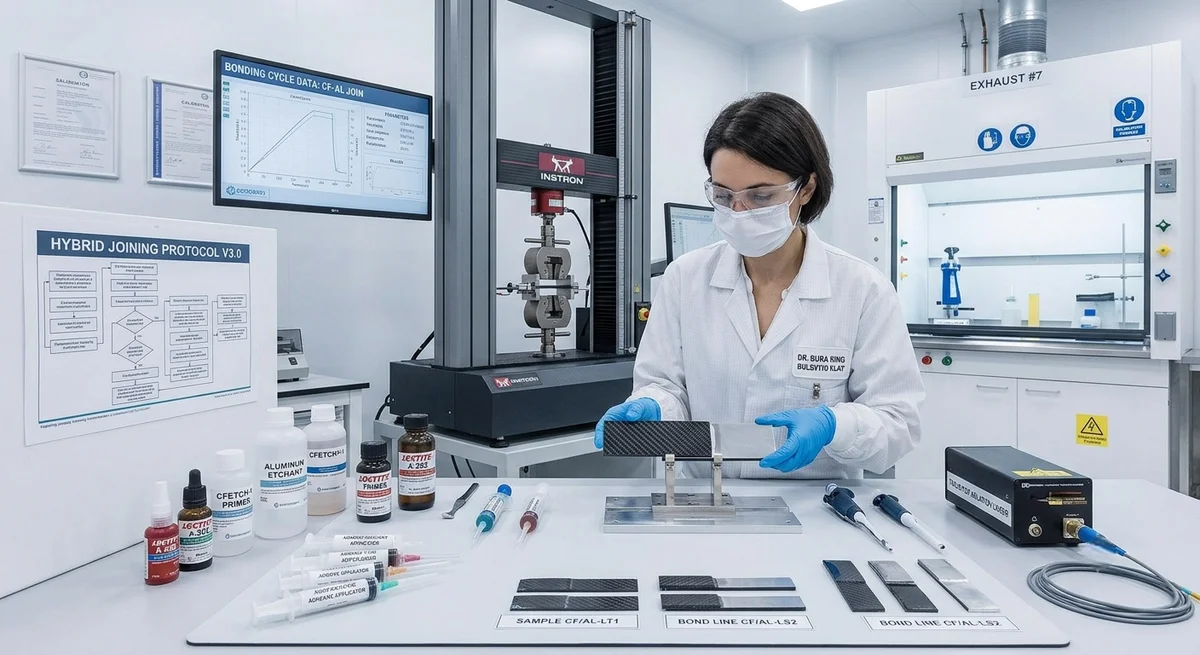
Comprehensive comparison of adhesive bonding and mechanical fastening methods for carbon fiber-to-metal joints — strength data, design guidelines, galvanic corrosion prevention, and application-specific recommendations.
Carbon Fiber to Metal Hybrid Bonding: Engineering Multi-Material Structures
Multi-material structures combining carbon fiber reinforced polymer (CFRP) with metals (aluminum, steel, titanium) are increasingly essential in automotive, aerospace, and industrial applications. As of 2026, over 40% of new aircraft structural designs and 25% of automotive body-in-white programs specify hybrid CFRP-metal joints. The two primary joining methods — adhesive bonding and mechanical fastening — have distinct performance profiles. This article provides B2B design engineers and procurement specialists with quantitative comparison data.
Joint Performance Comparison
| Property | Adhesive Bonding | Mechanical Fastening (Bolts/Rivets) | Hybrid (Bonded + Fastened) | Best for... |
|---|---|---|---|---|
| Static tensile strength (MPa) | 25–45 (single lap shear) | 150–350 (bearing strength) | 1.2–1.5× adhesive alone | Fastening for peak loads |
| Fatigue strength @10⁶ cycles | 50–70% of static | 20–35% of static | 55–75% of hybrid static | Adhesive for fatigue |
| Peel/cleavage resistance | Poor (2–8 N/mm) | Good (load path through bolt) | Good (fasteners arrest peel) | Fastening for peel loads |
| Weight penalty | Minimal (50–200 g/m² adhesive) | 5–15% of joint weight (fasteners) | Moderate | Adhesive for weight saving |
| Temperature range (°C) | −55 to 120 (epoxy); −55 to 230 (BMI) | −55 to 350+ (metal fasteners) | Limited by adhesive | Fastening for high temp |
| Galvanic corrosion risk | Low (adhesive is insulator) | High (direct metal-to-fiber contact) | Low (adhesive seals interface) | Adhesive for corrosion |
| Disassembly capability | No (permanent) | Yes (serviceable) | Partial | Fastening for maintenance |
| Production cycle time | 30 min–8 hours (cure) | 1–5 min per fastener | Cure + fastening time | Fastening for cycle time |
| Cost per joint (0.1 m² lap) | $8–25 | $15–50 (incl. drilling, sealant) | $20–65 | Adhesive for cost |
Adhesive Bonding: Design and Process
- Surface preparation is critical: Adhesive bond strength depends 70% on surface preparation quality. CFRP surface must be abraded (120–180 grit) or peel-ply treated, then solvent-cleaned. Metal surface requires grit-blasting (alumina 60–100 mesh) + silane primer for aluminum, or acid-etch + primer for titanium. Surface energy target: >45 mN/m for both substrates.
- Adhesive selection: Bisphenol A/F epoxy (two-part paste) — most common, 25–35 MPa lap shear, Tg 80–140°C. Film adhesive (epoxy with carrier) — for automated application, 30–45 MPa, better gap-filling. Acrylic (two-part) — faster cure (5–15 min), lower Tg (60–100°C), better peel. Polyurethane — flexible joints, 15–22 MPa, excellent impact resistance. BMI — high-temperature (up to 230°C), 28–35 MPa, aerospace only.
- Bondline thickness control: Optimal: 0.10–0.25 mm. Too thin (<0.05 mm) causes stress concentration and brittle failure; too thick (>0.50 mm) reduces shear strength by 30–50% due to increased peel stresses. Use glass microspheres (50–100 μm) or wire spacers for thickness control.
- Cure cycle: Room-temperature cure (23°C, 7–14 days to full strength) or elevated temperature cure (80–120°C, 60–120 min). Post-cure at 150–180°C for 2–4 hours for maximum Tg development. Vacuum bag pressure (80–95 kPa) for film adhesives; clamp pressure (100–300 kPa) for paste adhesives.
- Inspection methods: Ultrasonic C-scan (5–10 MHz) for void detection (>2 mm defect rejection). Shearography for disbond detection. Process control coupons tested per ASTM D1002 (lap shear) and ASTM D3165 (thick-adherend lap shear) for every production batch.
Mechanical Fastening: Design and Process
| Parameter | CFRP-to-Aluminum | CFRP-to-Steel | CFRP-to-Titanium | Design Note |
|---|---|---|---|---|
| Fastener material | Ti-6Al-4V or A286 CRES | A286 CRES or Inconel 718 | Ti-6Al-4V | Avoid aluminum fasteners (galvanic corrosion) |
| Hole quality | H8 (0–27 μm tolerance) | H8 | H8 | Drill with carbide step drill or diamond core drill |
| Edge distance / diameter | ≥3D (static), ≥4D (fatigue) | ≥3D / ≥4D | ≥2.5D / ≥3.5D | CFRP more sensitive to edge distance than metal |
| Clamp-up torque | 60–80% of metal torque spec | 50–70% | 70–85% | CFRP creep under sustained compression |
| Washer required | Yes — steel or Ti washer (both sides) | Yes | Yes | Distributes bearing stress, prevents crushing |
| Sealant required | Yes — wet-install with polysulfide or PTFE | Yes | Recommended | Prevents galvanic couple through hole |
| Bearing strength (MPa) | 350–550 (static) | 300–500 | 400–600 | 30–40% lower than metal-only joints |
Galvanic Corrosion Prevention
Carbon fiber is cathodic (+0.3 to +0.5 V vs SCE) relative to most structural metals, creating a galvanic cell when in direct electrical contact with an electrolyte (moisture, salt water). The corrosion rate of the anodic metal (aluminum, steel) accelerates 5–20× at the CF-metal interface. Prevention strategies:
- Complete electrical isolation: Use glass fiber scrim (0.1–0.3 mm) or epoxy bond ply between CF and metal. Resistance target: >10⁸ Ω across the joint (measured with 500 VDC megohmmeter per ASTM D257).
- Sealed fastener holes: Wet-install all fasteners with polysulfide or PTFE thread sealant. Apply faying-surface sealant (1–2 mm bead) around fastener head and nut.
- Fastener material selection: Titanium (Ti-6Al-4V) or corrosion-resistant steel (A286, Inconel 718) only. Avoid aluminum or cadmium-plated steel fasteners in CF joints.
- Environmental barrier: Apply epoxy primer (<25 μm) + polyurethane topcoat (50–80 μm) over all exposed CF-metal interfaces. Inspect annually for coating breakdown in corrosive environments (marine, chemical).
- Design for drainage: Avoid horizontal lap joints where moisture can accumulate. Provide drain holes at low points of enclosed hybrid structures. Seal all exposed edges.
Application-Specific Recommendations
| Industry | Typical Joint | Recommended Method | Rationale |
|---|---|---|---|
| Aerospace (primary structure) | CFRP skin to Ti subframe | Hybrid: adhesive + blind fasteners | Adhesive carries shear; fasteners provide fail-safe and peel resistance |
| Aerospace (secondary) | CFRP panel to Al frame | Adhesive bonding (film) | Weight saving, fatigue performance, smooth surface |
| Automotive (body structure) | CFRP roof to steel body | Adhesive + flow-drill screws | High-volume production, dissimilar metal isolation |
| Automotive (suspension) | CFRP spring to Al control arm | Mechanical (bolted with Ti fasteners) | Serviceability, high peel loads at bushing interface |
| Industrial (robotic arm) | CFRP tube to steel joint | Hybrid: adhesive + welded studs | High cyclic loads, torsional moment transfer |
| Marine (propeller shaft) | CFRP shaft to metal coupling | Hybrid: adhesive + keyway + clamp | Torsional load transfer, watertight seal, disassembly |
| Construction (retrofit) | CFRP plate to steel beam | Adhesive bonding | Thin profile, no drilling (avoids stress concentration) |
Design Checklist for B2B Engineers
- Define load spectrum: What are the peak, fatigue, and peel loads? Adhesive alone handles 50–70% of static UTS in fatigue; fasteners handle 20–35%. If peel loads >5 N/mm, use hybrid or mechanical.
- Assess temperature environment: Above 120°C continuous? Switch to BMI adhesive or mechanical fastening. Below −40°C? Check adhesive toughness (epoxies become brittle; consider polyurethane or acrylic).
- Evaluate production volume: <500 units/year — manual adhesive bonding with vacuum bag. 500–10,000 units/year — automated dispensing + fixture cure. >10,000 units/year — consider flow-drill fastening or induction-cured adhesives for cycle time.
- Factor in corrosion environment: Marine, chemical, or de-icing salt exposure requires full electrical isolation + sealed interfaces. Indoor environments (no condensation) can use simpler isolation.
- Design for inspectability: Provide access for ultrasonic C-scan or thermography. Bonded-only joints should have witness coupons from every batch. Mechanical joints should have torque-verification protocol.
- Plan for maintenance: If the joint must be disassembled during service life, use mechanical fastening or hybrid with accessible fasteners. Permanent adhesive-only joints that require cutting for disassembly increase maintenance cost 3–5×.
Q: Can adhesive bonding and mechanical fastening be combined, and what is the load-sharing behavior?
A: Yes — hybrid joints (adhesive + fasteners) are increasingly common in aerospace and automotive. The load-sharing is not simply additive — the adhesive carries primarily shear loads (60–85% of total shear transfer) while fasteners provide through-thickness clamping, peel resistance, and fail-safety. Testing by Airbus (2024) on CFRP-to-titanium hybrid joints showed: adhesive alone = 38 MPa lap shear; fasteners alone = 12 MPa bearing; hybrid = 42 MPa (only 10% higher than adhesive alone). However, fatigue life of hybrid joints is 5–8× longer than adhesive-only under high peel loads, and fastener inclusion prevents catastrophic failure if the bondline degrades. The fasteners should be designed as "arrestors" — they are not intended to carry primary load, but to stop peel propagation and ensure joint survival beyond bondline failure. Design rule: size fasteners for 30–50% of ultimate load to ensure fail-safety without overloading the CFRP bearing edge.
Q: What are the most common failure modes in CFRP-to-metal bonded joints, and how can they be prevented?
A: The five most common failure modes are: (1) Adhesive failure at CF interface (30% of field failures) — caused by inadequate CF surface preparation (low surface energy, mold release contamination). Prevention: peel-ply + atmospheric plasma treatment (O₂/Ar, 60–120 seconds) increases surface energy from 28–35 mN/m to >55 mN/m. (2) Cohesive failure within adhesive (25%) — caused by incorrect cure cycle or moisture contamination. Prevention: measure adhesive Tg by DSC (≥5°C margin above max service temperature); vacuum-dry prepregs and metal parts before bonding. (3) CF delamination (20%) — interlaminar failure within the composite, caused by out-of-plane peel stresses. Prevention: increase bond overlap length (>25 mm), taper CF edge (10:1 taper ratio), use z-pins or tufting in critical zones. (4) Metal corrosion (15%) — galvanic attack at damaged coating areas. Prevention: complete isolation + regular inspection of coating integrity. (5) Fatigue crack propagation from hole edges (10%, mechanical joints only). Prevention: use cold-expanded holes or interference-fit bushings for bolted joints in CFRP.
Q: What is the recommended overlap length for adhesive-bonded CFRP-to-metal lap joints?
A: The optimum overlap length depends on the load per unit width and the adhesive shear strength. For structural epoxy adhesives (25–35 MPa lap shear), the recommended overlap is 20–40 mm for typical aerospace loads (150–500 N/mm width). Below 15 mm overlap, the joint strength is approximately proportional to length (all adhesive is stressed). Above 40–50 mm, the joint becomes inefficient — the ends of the overlap carry most of the load while the center contributes little (load transfer saturation). A conservative design rule: L = P / (τ × b), where L = overlap length, P = applied load, τ = 8–12 MPa (design allowable for long-term, environmental reduction factor), b = bond width. This typically yields overlaps of 25–50 mm. For hybrid joints, the overlap can be reduced by 20–30% since fasteners share a portion of the load. For maximum fatigue performance, use 30–40 mm overlap with adhesive fillet at both ends (3–5 mm radius) to reduce peel stress concentration.
Part of topic
Related Articles
- Bio-Based Carbon Fiber Precursors: Lignin and Polyethylene for Low-Cost Production
- Large-Tow Carbon Fiber Cost Analysis: 48K vs 60K Price-Performance Comparison
- Carbon Fiber-Resin Interface Bonding: Surface Treatment and Coupling Agent Optimization
- Digital Twin for Carbon Fiber Manufacturing: Real-Time Process Monitoring and Defect Prevention
- Thermoplastic Carbon Fiber Welding for Automotive: Ultrasonic and Induction Welding Process Windows
- Large-Tow Carbon Fiber Wet Spinning: Process Optimization for 48K/60K Production Efficiency
Interested in Our Products?
Contact our team for competitive pricing and technical specifications.
Get a QuoteRelated Products

Carbon fiber standard plate-3k stripe
Lightweight, ultra-rigid standard sheets for drone fuselages, robot housings, facades and structural applications.

Carbon Fiber Plate — 3K Twill T700 1.5mm
Thin 1.5mm carbon fiber plate with 3K twill weave surface. Lightweight and stiff, commonly used for covers, panels, drone bodies, and applications requiring a premium aesthetic appearance.

Square Carbon Fiber Tube — 3K Twill T700
Square cross-section carbon fiber tube manufactured with 3K twill weave for torsional strength. Preferred for structural frames, trusses, and support columns where rectangular geometry offers design flexibility.

Carbon Fiber Plate — 3K Twill T700 3.0mm
Medium-thickness 3.0mm carbon fiber plate offering significantly higher load capacity while maintaining attractive 3K twill finish. Suitable for structural brackets, reinforcement plates, and load-bearing panels.

Carbon Fiber Plate — UD Unidirectional T700
Unidirectional carbon fiber plate with all fibers oriented in a single direction for maximum strength along the fiber axis. Essential for structural reinforcements, splints, and applications where load direction is predictable.