
Technical analysis of galvanic corrosion risks when carbon fiber composites contact metals in marine and aerospace environments — covering corrosion mechanisms, material pairing tables, isolation strategies, and field performance data for long-life structures.
Introduction: The Electrochemical Challenge of Carbon Fiber-Metal Contact
Carbon fiber is electrically conductive with a resistivity of 1.5–3.0 × 10⁻³ Ω·cm, placing it in the noble (cathodic) region of the galvanic series with a potential of +0.3 to +0.5 V vs. saturated calomel electrode (SCE) in seawater. When carbon fiber reinforced polymer (CFRP) contacts a less noble metal — aluminum alloys (−0.8 to −1.0 V SCE), steel (−0.6 to −0.7 V SCE), or magnesium (−1.6 V SCE) — in the presence of an electrolyte (seawater, acid rain, condensation), a galvanic cell forms. The potential difference between CFRP and 6061-T6 aluminum (1.2–1.5 V) drives an electrochemical current that can corrode the metal at rates up to 2–5 mm/year in aggressive marine environments — 10–50× faster than the same metal's corrosion rate in the absence of galvanic coupling.
The marine and aerospace industries, which increasingly rely on CFRP for primary and secondary structures, have invested heavily in understanding and mitigating galvanic corrosion. The global commercial aircraft fleet, currently operating with approximately 35–50% CFRP by weight (Boeing 787 and Airbus A350), has accumulated over 500 million flight hours of galvanic corrosion experience. In marine applications, CFRP-aluminum superstructures on naval vessels and CFRP-hulled yachts have demonstrated the critical importance of proper galvanic isolation design. This article provides a comprehensive analysis of galvanic corrosion mechanisms, material compatibility data, and field-validated prevention strategies.
Galvanic Series of Common Materials in Seawater
| Material | Potential vs SCE (V) | Area Effect Factor | Typical Corrosion Rate Unprotected (mm/year) | Risk with CFRP Contact |
|---|---|---|---|---|
| Magnesium alloys (AZ31, AZ91) | −1.60 to −1.50 | 8–15 | 0.5–2.0 | Critical — catastrophic corrosion possible within weeks |
| Zinc (galvanized) | −1.05 to −0.95 | 6–10 | 0.02–0.10 | High — sacrificial protection consumes zinc rapidly |
| Aluminum 5xxx series (5052, 5083) | −0.90 to −0.80 | 5–8 | 0.10–0.30 | Very high — requires insulation |
| Aluminum 6xxx series (6061, 6082) | −0.85 to −0.75 | 5–8 | 0.08–0.25 | Very high — requires insulation |
| Aluminum 7xxx series (7075, 7050) | −0.80 to −0.70 | 4–7 | 0.05–0.15 | High — requires careful insulation design |
| Carbon steel / low-alloy steel | −0.65 to −0.55 | 3–6 | 0.10–0.50 | Moderate-high — insulation recommended |
| Stainless steel 316L (passive) | −0.10 to +0.15 | 1–2 | <0.01 | Low — small potential difference |
| Stainless steel 304 (passive) | −0.05 to +0.20 | 1–2 | <0.01 | Low — small potential difference |
| Titanium Ti-6Al-4V | −0.05 to +0.10 | 1–2 | <0.01 | Very low — compatible |
| Nickel-based superalloys (Inconel 625, 718) | −0.05 to +0.15 | 1–2 | <0.01 | Very low — compatible |
| Copper / brass / bronze | −0.25 to +0.05 | 2–3 | 0.02–0.10 | Low-moderate |
| Carbon fiber (CFRP, fiber direction) | +0.30 to +0.50 | — | 0 (cathode) | Acts as cathode — drives metal corrosion |
| Graphite (bulk) | +0.40 to +0.60 | — | 0 (cathode) | Acts as cathode — drives metal corrosion |
The "area effect factor" is critical: CFRP has a much larger surface area (the cathode) than the exposed metal surface (the anode) in most joint configurations. Galvanic corrosion current density is proportional to the cathode-to-anode area ratio — a ratio of 100:1 (typical for a CFRP panel bolted to a small aluminum bracket) results in a corrosion rate approximately 100× higher than the same metal's free corrosion rate. This area effect means that small metal fasteners in large CFRP structures are at extreme risk.
Key Factors Influencing Galvanic Corrosion Severity
- Electrolyte conductivity and availability: Galvanic corrosion requires a continuous electrolyte path. In marine environments (seawater conductivity 4–5 S/m), galvanic currents can flow over distances of 0.5–2 meters. In aerospace environments (condensation, humidity, runway de-icing fluids), the electrolyte film is thinner and more intermittent, limiting galvanic effects to within 5–50 mm of the bimetallic junction. The duration of electrolyte exposure is equally important: a marine vessel in continuous seawater contact experiences galvanic corrosion 24/7, while an aircraft experiences intermittent wet-dry cycles.
- Temperature: Galvanic corrosion rates increase with temperature following an Arrhenius relationship — approximately doubling for every 25°C increase. At 60°C (typical under an aircraft fuselage on a tarmac), the corrosion rate is 4–6× higher than at 15°C. In marine engine rooms with ambient temperatures of 40–50°C, accelerated galvanic corrosion of aluminum-CFRP joints has been documented at 3–5 mm/year without proper isolation.
- Surface condition of the metal: Anodized aluminum (MIL-A-8625 Type II, 5–25 µm coating) provides significant galvanic protection — reducing corrosion rates by 80–95% compared to bare aluminum. However, anodized coatings are brittle and can crack under mechanical loading, exposing bare aluminum at fastener holes, joint interfaces, and abrasion points. A single scratch exposing 1 mm² of bare aluminum on an anodized bracket in contact with CFRP creates a localized anode with a cathode-to-anode area ratio of 10,000:1, leading to rapid pitting at the scratch site.
- Fastener material selection: Fasteners are the most common galvanic corrosion path in CFRP-metal structures. The table below shows recommended fastener materials for different CFRP-metal joint combinations. Note that even titanium fasteners (Ti-6Al-4V, potential −0.05 V SCE) can cause galvanic corrosion of aluminum substrates if the fastener is in direct contact with both CFRP and aluminum — creating a three-material galvanic couple.
- Coating and sealant integrity: The single most important factor in galvanic corrosion prevention is the integrity of the isolation barrier between CFRP and the metal. Wet-installation with polysulfide sealant (e.g., PR-1776 or MC-238) or PTFE-impregnated anodized coatings provides the primary barrier. Sealant bond line thickness should be 0.5–1.5 mm for adequate electrical isolation (breakdown voltage >10 kV at 1.0 mm thickness). Any gap or disbond in the sealant creates a localized galvanic cell.
- Oxygen availability at the cathode: CFRP's cathodic reaction consumes dissolved oxygen: O₂ + 2H₂O + 4e⁻ → 4OH⁻. In low-oxygen environments (crevices, deep seawater below the thermocline), the oxygen reduction reaction is mass-transport-limited, and the galvanic corrosion rate is lower. In aerated, turbulent flow conditions (near the waterline on a marine vessel, or in rain-runoff channels on an aircraft), oxygen replenishment is rapid, and galvanic corrosion is maximized.
Galvanic Isolation Strategies and Best Practices
| Isolation Method | Material / Specification | Dielectric Strength | Typical Thickness | Effectiveness | Application Cost |
|---|---|---|---|---|---|
| Structural adhesive bonding | Aerospace epoxy film adhesive (FM-300, Hysol EA-9394) | 15–25 kV/mm | 0.1–0.5 mm bond line | Excellent — full electrical isolation if continuous | Moderate — requires surface prep and cure cycle |
| Polysulfide sealant wet-installation | PR-1776, MC-238, or equivalent | 10–15 kV/mm | 0.5–1.5 mm | Excellent — self-healing, compressible | Low — easily applied, 24-hour cure |
| Fiberglass isolation ply | E-glass or S-glass prepreg, 0.1–0.3 mm per ply | 20–30 kV/mm | 0.3–1.0 mm (2–4 plies) | Very good — co-cured with CFRP structure | Moderate — co-cured, no extra process step |
| PTFE-coated fastener | Ti-6Al-4V fastener with PTFE coating (Hi-Lok, Cherry) | 40–60 kV per coating | 12–25 µm coating | Good — pure PTFE is chemically inert | Moderate — premium fastener cost |
| Ceramic-filled epoxy coating | Al₂O₃ or SiO₂-filled epoxy, spray applied | 12–18 kV/mm | 0.2–0.5 mm | Good — requires careful application | Low-moderate |
| Anodizing (aluminum only) | MIL-A-8625 Type II (sulfuric), Type III (hard coat) | 30–50 kV per 10 µm (Type III) | 5–25 µm (Type II), 25–75 µm (Type III) | Moderate — brittle, cracks under load | Low — standard process |
| Cadmium plating + chromate | MIL-PRF-14068 (cadmium), QQ-P-416 | N/A (sacrificial coating) | 8–15 µm | Moderate — sacrificial, toxic (RoHS concerns) | Low-moderate |
Case Study: Galvanic Corrosion in CFRP-Aluminum Marine Superstructure
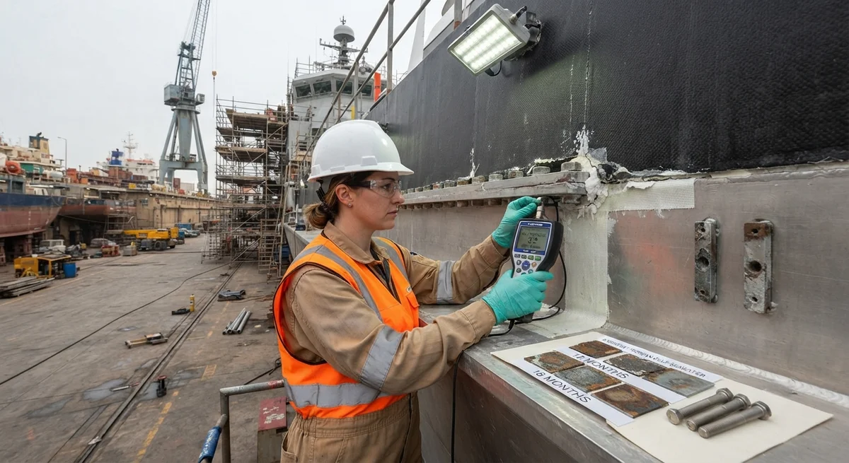
A 45-meter aluminum patrol vessel was refitted with a CFRP superstructure (10-meter length, 3-meter height) in 2017. The CFRP superstructure was bonded to the aluminum hull using a combination of adhesive bonding (epoxy film adhesive) and mechanical fastening with titanium bolts (every 200 mm along the flange). Despite the use of titanium fasteners, corrosion was detected at the CFRP-aluminum interface during a routine dry-dock inspection after 18 months of service in the Persian Gulf (seawater temperature 28–34°C, salinity 4.0–4.2%).
- Observed damage: Pitting corrosion at 62 of 240 bolted joint locations (26% failure rate), with pit depths of 0.3–1.8 mm on the 4 mm thick aluminum flange. The worst-affected areas were at the aft end of the superstructure where exhaust heat (50–70°C surface temperature) accelerated corrosion.
- Root cause analysis: The polysulfide sealant used for wet-installation of the bolts had disbonded from the CFRP surface in high-temperature areas. The disbonded gap allowed seawater ingress, creating a confined electrolyte path between the CFRP (cathode) and the aluminum flange (anode). The cathode-to-anode area ratio at each failed joint was estimated at 5,000:1, driving an accelerated pitting rate of 0.8–1.2 mm/year — 40–60× the unprotected corrosion rate of 5083 aluminum in the Persian Gulf (0.02 mm/year).
- Remediation: All 240 joints were reworked: the aluminum flange was re-anodized (Type III hard coat, 50 µm), joints were redesigned with a 2 mm thick fiberglass isolation layer (4 plies of S-glass prepreg) co-cured onto the CFRP flange, and bolts were wet-installed with a high-temperature polysulfide sealant (PR-1776 HT, rated to 120°C). After remediation, the vessel has operated for 5 years without detectable corrosion at the reworked joints.
Design Guidelines for Galvanic Corrosion Prevention
- Design for drainage: All CFRP-metal joints in marine or outdoor aerospace applications should be designed to prevent electrolyte entrapment. Provide drainage paths, avoid horizontal ledges, and orient flange surfaces to shed water. A minimum drainage hole diameter of 6 mm every 300 mm is recommended for enclosed cavities.
- Use noble metal fasteners: Titanium (Ti-6Al-4V or Ti-6Al-2Sn-4Zr-2Mo) or Inconel 718 fasteners are preferred for CFRP-metal joints. Never use carbon steel, low-alloy steel, or 400-series stainless steel fasteners in CFRP joints exposed to electrolytes. If aluminum fasteners must be used (for weight reasons), they must be coated with PTFE or hard anodized and wet-installed with sealant.
- Glass fiber isolation layer: Co-cure 2–4 plies of E-glass or S-glass prepreg (total 0.3–1.0 mm) on the CFRP surface at every metal interface. The glass layer is electrically insulating (resistivity >10¹⁴ Ω·cm) and prevents direct carbon fiber-to-metal contact even if the sealant fails. This is the single most reliable isolation method and is widely specified in aerospace and marine standards.
- Sacrificial anode protection: In marine applications, aluminum or zinc sacrificial anodes can protect the metal component in a CFRP-metal assembly. The anode must be electrically connected to the metal component (not to the CFRP). A typical zinc anode (2–5 kg) protects approximately 10–20 m² of aluminum surface in seawater for 2–3 years. However, the CFRP cathode drives a higher demand for sacrificial anode current than an all-metal structure — expect 3–5× higher anode consumption rates.
- Periodic inspection: CFRP-metal joints in corrosive environments should be inspected annually. Inspection methods include: visual inspection for sealant cracks or gaps, thermographic inspection to detect moisture ingress in bonded joints, ultrasonic inspection for metal thinning at joint locations, and electrical isolation resistance measurement (minimum 1 MΩ at 500 V DC between CFRP and metal).
Frequently Asked Questions
Can stainless steel fasteners be used safely with carbon fiber composites?
Stainless steel grades 316L or 304L (passive) are acceptable for CFRP joints in benign environments (indoor, controlled humidity) but not recommended for marine or external aerospace applications. The potential difference between 316L passive (+0.15 V SCE) and CFRP (+0.35 V) is only 0.2 V — insufficient to drive aggressive galvanic corrosion in most conditions. However, if the stainless steel becomes active (e.g., in a crevice or low-oxygen environment), its potential drops to −0.2 to −0.4 V SCE, increasing the potential difference to 0.6–0.8 V — enough to cause significant corrosion of the fastener itself (crevice corrosion) and accelerated corrosion of any less-noble metal in the assembly. For critical applications, titanium or Inconel fasteners are strongly preferred over stainless steel.
How does galvanic corrosion affect carbon fiber itself?
Carbon fiber is the cathode in the galvanic cell and does not corrode. However, three secondary effects can damage the CFRP: (1) Hydrogen evolution: At high galvanic current densities (>1 mA/cm²), the cathode reaction on CFRP produces hydrogen gas (2H₂O + 2e⁻ → H₂ + 2OH⁻). Hydrogen can diffuse into the epoxy matrix at the fiber-matrix interface, causing microcracking and reducing interlaminar shear strength by 10–25% after prolonged exposure. (2) Alkaline degradation: The cathodic reaction generates hydroxide ions (OH⁻), raising the local pH to 10–12 at the CFRP surface. High pH can attack the epoxy matrix (hydrolysis of ester linkages), particularly in amine-cured epoxy systems, causing surface softening and etch pitting. (3) Galvanic-induced debonding: The accumulation of corrosion products (aluminum hydroxide, iron oxides) at the bimetallic interface generates expansive stresses (up to 3 MPa for aluminum corrosion products) that can mechanically debond the CFRP from the metal substrate or sealant.
What are the relevant standards for galvanic corrosion testing of CFRP-metal assemblies?
The key standards are: ASTM G71 (Standard Guide for Conducting and Evaluating Galvanic Corrosion Tests in Electrolytes) — the primary test method for measuring galvanic current and potential between dissimilar materials; ISO 9227 (Neutral Salt Spray Test — NSS) — accelerated corrosion testing for coated and uncoated CFRP-metal assemblies, typically 500–1,000 hours for marine qualification; ASTM B117 (Standard Practice for Operating Salt Spray Apparatus) — similar to ISO 9227, widely used in North America for aerospace qualification; MIL-STD-889 (Dissimilar Metals) — the US Department of Defense standard defining acceptable and unacceptable metal pairings, including CFRP; and NACE TM0169 (Standard Guide for Laboratory Corrosion Testing of Metals). For aerospace-specific galvanic testing, Boeing D6-82481 and Airbus AITM 6-0003 specify test configurations and acceptance criteria for CFRP-metal joints.
Is galvanic corrosion a concern when carbon fiber contacts aluminum in dry indoor environments?
Galvanic corrosion requires an electrolyte — without moisture, no significant electrochemical reaction occurs. In dry, indoor environments (relative humidity <40%, no condensation), CFRP-aluminum contacts are generally safe. However, three caveats apply: (1) Humidity cycling: Even in "dry" indoor environments, the CFRP-metal interface can experience localized condensation during temperature changes (e.g., night-time temperature drops in unconditioned industrial buildings). (2) Hygroscopic effects: Epoxy resin absorbs 0.5–1.5% moisture by weight from ambient humidity, creating a thin electrolyte layer within the resin that enables low-level galvanic activity (corrosion rates of 0.01–0.05 mm/year — negligible for most applications but a concern for precision assemblies). (3) Contamination: Fingerprints, dust, or processing residues at the joint can absorb atmospheric moisture and create localized galvanic cells. For non-structural, indoor CFRP-metal joints, applying a thin layer of paint or lacquer to the joint interface is sufficient to prevent corrosion.
How do galvanic corrosion risks differ between aerospace and marine applications?
The fundamental mechanisms are the same, but the severity differs dramatically. In marine applications: continuous electrolyte (seawater) exposure means uninterrupted galvanic activity; high conductivity (4–5 S/m) allows galvanic currents to flow over meters; biofouling and sediment create differential aeration cells that compound galvanic effects; and cathodic protection systems (impressed current or sacrificial anodes) interact with CFRP cathodes. In aerospace applications: electrolyte exposure is intermittent (rain, condensation, de-icing fluids, runway wash); conductivity is lower (de-icing fluids: 0.1–1 S/m; condensation: 10⁻³ S/m); thermal cycling (−55°C to +70°C) cycles the joint interface, potentially fatiguing sealant bonds; electrical bonding and lightning strike protection requirements add complexity (CFRP structures must be electrically bonded to metallic airframe components, creating intentional electrical paths that must also be galvanically managed); and the consequences of corrosion-induced structural failure are catastrophic. As a rule of thumb, a galvanic corrosion control design validated for marine exposure provides adequate protection for aerospace, but the reverse is not true.
Conclusion
Galvanic corrosion between carbon fiber composites and metals is a well-understood electrochemical phenomenon that can be effectively managed through proper design practices. The key principles for B2B buyers and design engineers are: (1) Titanium and stainless steel 316L are the most compatible common metals for direct CFRP contact; aluminum and steel always require galvanic isolation. (2) A co-cured fiberglass isolation layer (2–4 plies, 0.3–1.0 mm) provides the most reliable long-term protection by eliminating direct carbon fiber-to-metal contact. (3) Wet-installation of fasteners with polysulfide or epoxy sealant is essential for any bolted CFRP-metal joint exposed to electrolytes. (4) The cathode-to-anode area ratio must be minimized — avoid small metal components in large CFRP structures without thorough isolation. (5) Regular inspection and maintenance of the isolation barrier is necessary, as sealant degradation and mechanical damage are the most common failure modes. With proper design, CFRP-metal hybrid structures have demonstrated 20+ year service lives in both marine and aerospace environments without significant galvanic degradation.
Part of topic
Related Articles
- Bio-Based Carbon Fiber Precursors: Lignin and Polyethylene for Low-Cost Production
- Large-Tow Carbon Fiber Cost Analysis: 48K vs 60K Price-Performance Comparison
- Carbon Fiber-Resin Interface Bonding: Surface Treatment and Coupling Agent Optimization
- Digital Twin for Carbon Fiber Manufacturing: Real-Time Process Monitoring and Defect Prevention
- Thermoplastic Carbon Fiber Welding for Automotive: Ultrasonic and Induction Welding Process Windows
- Large-Tow Carbon Fiber Wet Spinning: Process Optimization for 48K/60K Production Efficiency
Interested in Our Products?
Contact our team for competitive pricing and technical specifications.
Get a QuoteRelated Products

Carbon fiber standard plate-3k stripe
Lightweight, ultra-rigid standard sheets for drone fuselages, robot housings, facades and structural applications.

Carbon Fiber Plate — 3K Twill T700 1.5mm
Thin 1.5mm carbon fiber plate with 3K twill weave surface. Lightweight and stiff, commonly used for covers, panels, drone bodies, and applications requiring a premium aesthetic appearance.

Square Carbon Fiber Tube — 3K Twill T700
Square cross-section carbon fiber tube manufactured with 3K twill weave for torsional strength. Preferred for structural frames, trusses, and support columns where rectangular geometry offers design flexibility.

Carbon Fiber Plate — 3K Twill T700 3.0mm
Medium-thickness 3.0mm carbon fiber plate offering significantly higher load capacity while maintaining attractive 3K twill finish. Suitable for structural brackets, reinforcement plates, and load-bearing panels.

Carbon Fiber Plate — UD Unidirectional T700
Unidirectional carbon fiber plate with all fibers oriented in a single direction for maximum strength along the fiber axis. Essential for structural reinforcements, splints, and applications where load direction is predictable.