
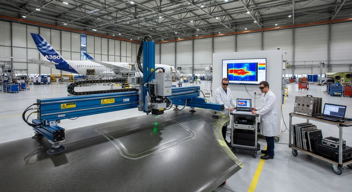
Laser ultrasonic (LUT) inspection has emerged as the preferred non-destructive evaluation (NDE) method for carbon fiber composite repairs in aerospace MRO environments. This article details the operating principles of LUT systems, the specific inspection criteria mandated by Boeing and Airbus for re
Why Laser Ultrasonic Inspection for Carbon Fiber?
Carbon fiber reinforced polymer (CFRP) now accounts for over 50% of structural weight on modern commercial aircraft — the Boeing 787 Dreamliner at approximately 50% and the Airbus A350 XWB at 53%. As these composite-intensive airframes age and enter their first major repair cycles, maintenance, repair, and overhaul (MRO) facilities face the challenge of reliably detecting hidden damage — delaminations, disbonds, impact damage, and porosity — in complex curved structures without introducing couplant contamination or requiring contact with the part surface.
Laser ultrasonic (LUT) inspection solves this problem by using a pulsed laser to generate ultrasound at the part surface and a separate laser interferometer to detect the reflected ultrasonic waves. The system operates in a fully non-contact, dry-coupled mode, making it suitable for inspecting honeycomb panels, sandwich structures, tape-laid skins, and bonded repairs on both flat and contoured surfaces — including areas inaccessible to conventional contact transducers.
Operating Principles of Laser Ultrasonic Systems
A LUT inspection system operates on the thermoelastic generation principle. A Q-switched Nd:YAG or CO₂ laser delivers a short-duration (typically 5–20 nanosecond) pulse to the CFRP surface. Localized rapid heating — on the order of 5–10°C per pulse — causes thermoelastic expansion that generates a broadband ultrasonic wave (0.5–20 MHz) that propagates through the composite thickness. The ultrasonic wave reflects from the back wall, from ply interfaces, and from any internal defects. A detection laser — typically a frequency-stabilized continuous-wave or long-pulse laser — measures surface displacement via a Fabry-Pérot or two-wave mixing interferometer.
The inspection can be configured in two modes:
- Pitch-catch (guided wave) mode: Generation and detection lasers are separated by a fixed standoff distance (typically 10–50 mm). The ultrasonic wave propagates laterally along the part surface. Sensitive to near-surface delaminations, disbonds in sandwich panels, and skin-to-core disbonds. Scan rates: 10–100 m² per hour depending on grid resolution.
- Through-thickness (pulse-echo) mode: Generation and detection lasers are co-located or closely spaced. The ultrasonic wave propagates through the thickness and reflects from the back wall. Delaminations, porosity clusters, and impact damage appear as intermediate echoes between the front-wall and back-wall reflections. Scan rates: 1–10 m² per hour at 1 mm grid spacing.
Boeing and Airbus Repair Station Requirements
Both OEMs have published specific requirements for NDE methods used in composite repair stations. The following table summarizes the key inspection criteria from Boeing NCFRP-01 (Revision G) and Airbus ABP 3-0002 (Issue 6):
| Requirement | Boeing NCFRP-01 (Rev G) | Airbus ABP 3-0002 (Issue 6) |
|---|---|---|
| Maximum allowable delamination size (non-critical zone) | < 1.0 inch (25.4 mm) diameter | < 20 mm diameter |
| Maximum allowable delamination size (critical zone) | < 0.5 inch (12.7 mm) diameter | < 10 mm diameter |
| Minimum detectable defect size (certified equipment) | 0.25 inch (6.35 mm) | 5 mm |
| Porosity acceptance limit | < 2% void content by volume over any 2 inch × 2 inch (50 × 50 mm) area | < 1.5% void content by volume over any 50 × 50 mm area |
| Disbond acceptance (honeycomb panels) | < 1.0 inch (25.4 mm) disbond between skin and core | < 15 mm disbond between skin and core |
| Inspection grid resolution required | 0.05 inch (1.27 mm) for critical zones; 0.10 inch (2.54 mm) for non-critical | 1 mm for critical zones; 2 mm for non-critical |
| Couplant requirements | Dry-coupled or non-contact methods preferred; water-based couplant allowed only with written approval | Dry-coupled or non-contact required for prepreg repair patches; gel couplant allowed for parent laminate inspection in non-critical areas |
| Reference standard requirements | Calibration panel with 0.25 in, 0.5 in, and 1.0 in flat-bottom holes at ply midpoints; annual recertification | Calibration panel with 5 mm, 10 mm, and 20 mm flat-bottom holes; recertification every 6 months |
| Operator certification | NAS 410 Level II or III (UT method) | EN 4179 / NAS 410 Level II or III (UT method) |
Laser ultrasonic systems that meet or exceed these detection sensitivity thresholds — with demonstrated probability of detection (POD) of 90/95 for the minimum defect sizes listed above — are qualified as alternative NDE methods under both OEM specifications. Several commercially available LUT systems (including products from iPhoton Solutions, Luna Innovations, and Tecnatom) have been qualified to these standards for specific CFRP repair scenarios.
Comparative Performance: LUT vs. Conventional Ultrasonic Testing
MRO facilities evaluating LUT adoption must weigh several performance trade-offs against conventional pulse-echo ultrasonic testing (UT) with contact transducers:
- Inspection speed: LUT achieves 5–50× faster area coverage than manual contact UT in scanning mode. A single-sided repair patch (0.5 m²) can be scanned by LUT in 3–10 minutes versus 45–90 minutes for manual contact UT at equivalent 1 mm grid resolution.
- Geometric flexibility: LUT maintains coupling on curved surfaces (radius down to 5 mm) and through complex geometries where contact transducers lose coupling. This includes repair patches on wing leading edges, engine nacelle inlets, and fuselage belly fairings.
- Couplant elimination: Dry-coupled operation eliminates the need for water, gel, or immersion tanks — critical for in-situ repairs where couplant containment is impractical. It also eliminates the risk of moisture ingress into honeycomb cores during inspection.
- Detection sensitivity: LUT and conventional UT show equivalent detection sensitivity for delaminations ≥ 10 mm and porosity ≥ 2%. For smaller defects (5–10 mm), LUT sensitivity depends on laser spot size and interferometer bandwidth. Modern LUT systems with 1–3 mm laser spot diameters achieve POD comparable to 5–10 MHz contact transducers for thin to moderate CFRP laminates (2–15 mm thickness).
- Equipment cost: A fully integrated LUT scanning system ranges from $180,000 to $450,000, versus $25,000–$80,000 for a conventional UT flaw detector with manual scanning bridge. However, for facilities processing 50+ composite repairs per month, the inspection time savings typically yield ROI within 12–18 months.
Integration into Repair Station Workflows
Certified Boeing and Airbus repair stations that have adopted LUT typically follow this inspection workflow:
- Step 1 — Pre-repair scan: The damaged area is scanned with LUT to define the damage boundary, quantify delamination extent, and identify any impact damage below the visible surface. Scan results are recorded as C-scan images with depth-gated layers.
- Step 2 — Damage removal verification: After scarfing or step-sanding to remove damaged plies, the repair cavity is re-scanned to confirm complete damage removal. Any residual delamination extending beyond the repair boundary is flagged for additional ply removal.
- Step 3 — Repair patch inspection: The procured or shop-fabricated repair patch (prepreg or wet layup) is scanned prior to installation to verify ply alignment, detect any fabrication defects, and confirm the absence of foreign object debris (FOD) between plies.
- Step 4 — Post-cure inspection: After the repair patch is installed and cured (typically under vacuum bag at 120–180°C), the completed repair is scanned. Acceptance criteria: no detectable delaminations at the repair patch boundary, void content below 1.5%, and full bond-line integrity across the repair interface.
FAQ: Laser Ultrasonic Inspection of CFRP
Can LUT inspect through paint, primer, or lightning strike protection layers?
Yes, with limitations. Thin paint layers (< 150 µm) and primer coatings are transparent to the generation and detection lasers. Thicker coatings, erosion shields, and copper/aluminum lightning strike protection (LSP) mesh attenuate the ultrasonic signal. For LSP-coated surfaces, the generation laser energy must be increased by 30–50% and the detection interferometer gain adjusted accordingly. Some thick LSP layers (expanded copper foil > 100 µm) require localized removal of the LSP layer in the scan area. Boeing NCFRP-01 specifies a surface reflectance test method to verify adequate laser coupling through coatings prior to inspection.
What training is required for LUT system operators in aerospace MRO?
Operators require NAS 410 or EN 4179 certification in the ultrasonic testing (UT) method at Level II or III, plus manufacturer-specific training on the LUT system (typically 40–80 hours of hands-on training covering system setup, calibration on reference standards, scan parameter optimization, and C-scan interpretation). The combined qualification path typically takes 3–6 months for a Level II operator to achieve full LUT competency. Airbus and Boeing both require documented evidence of LUT-specific training before authorizing an operator to perform production LUT inspections on their aircraft.
How does LUT detect kissing bonds or weak adhesive bonds in repairs?
Kissing bonds — where two surfaces are in intimate contact without adequate adhesive strength — are the most challenging defect to detect with any ultrasonic method, including LUT. The ultrasonic reflection amplitude from a kissing bond is significantly lower than from a disbond (air gap), because the acoustic impedance mismatch is minimal. LUT can detect kissing bonds through nonlinear ultrasonic techniques (second harmonic generation, sideband modulation) that are sensitive to the non-linear acoustic response of partially bonded interfaces. However, these nonlinear methods require higher laser energy and longer scan times. For production inspection, OEM repair manuals typically rely on the combination of LUT pulse-echo imaging and process control (documented adhesive thickness, surface preparation, and cure cycle parameters) to mitigate kissing bond risk, rather than attempting to detect kissing bonds directly via NDE alone.
Part of topic
Related Articles
- Bio-Based Carbon Fiber Precursors: Lignin and Polyethylene for Low-Cost Production
- Large-Tow Carbon Fiber Cost Analysis: 48K vs 60K Price-Performance Comparison
- Carbon Fiber-Resin Interface Bonding: Surface Treatment and Coupling Agent Optimization
- Digital Twin for Carbon Fiber Manufacturing: Real-Time Process Monitoring and Defect Prevention
- Thermoplastic Carbon Fiber Welding for Automotive: Ultrasonic and Induction Welding Process Windows
- Large-Tow Carbon Fiber Wet Spinning: Process Optimization for 48K/60K Production Efficiency
Interested in Our Products?
Contact our team for competitive pricing and technical specifications.
Get a QuoteRelated Products

Carbon fiber standard plate-3k stripe
Lightweight, ultra-rigid standard sheets for drone fuselages, robot housings, facades and structural applications.

Carbon Fiber Plate — 3K Twill T700 1.5mm
Thin 1.5mm carbon fiber plate with 3K twill weave surface. Lightweight and stiff, commonly used for covers, panels, drone bodies, and applications requiring a premium aesthetic appearance.

Square Carbon Fiber Tube — 3K Twill T700
Square cross-section carbon fiber tube manufactured with 3K twill weave for torsional strength. Preferred for structural frames, trusses, and support columns where rectangular geometry offers design flexibility.

Carbon Fiber Plate — 3K Twill T700 3.0mm
Medium-thickness 3.0mm carbon fiber plate offering significantly higher load capacity while maintaining attractive 3K twill finish. Suitable for structural brackets, reinforcement plates, and load-bearing panels.

Carbon Fiber Plate — UD Unidirectional T700
Unidirectional carbon fiber plate with all fibers oriented in a single direction for maximum strength along the fiber axis. Essential for structural reinforcements, splints, and applications where load direction is predictable.