
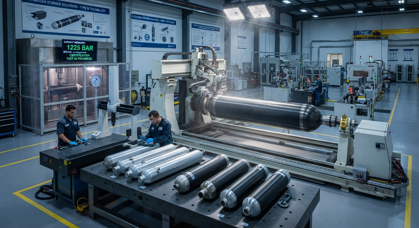
High-Pressure Composite Gas Cylinders: Carbon Fiber Wrapped Aluminum vs All-Composite Design Trade-offs The global composite gas cylinder market is projected to grow from $3.8 billion in 2025 to $7.9 billion by 2034, at a CAGR of 8.5%, driven by the expanding hydrogen economy, compressed natural…
High-Pressure Composite Gas Cylinders: Carbon Fiber Wrapped Aluminum vs All-Composite Design Trade-offs
The global composite gas cylinder market is projected to grow from $3.8 billion in 2025 to $7.9 billion by 2034, at a CAGR of 8.5%, driven by the expanding hydrogen economy, compressed natural gas (CNG) vehicle adoption, industrial gas storage requirements, and the growing use of lightweight cylinders in aerospace and defense applications. Within this market, two primary carbon fiber composite cylinder architectures compete for dominance: Type III cylinders (carbon fiber fully wrapped over a metallic liner, typically aluminum 6061-T6) and Type IV cylinders (carbon fiber fully wrapped over a non-metallic polymeric liner, typically high-density polyethylene (HDPE) or polyamide (PA)). Each design approach presents distinct advantages and trade-offs in weight, cost, fatigue life, permeation characteristics, and manufacturing complexity.
For B2B buyers — including hydrogen storage system integrators, CNG vehicle conversion specialists, industrial gas suppliers, and composite cylinder OEMs — understanding the technical differences between Type III and Type IV composite cylinder designs is essential for selecting the appropriate technology for each application. This article provides a comprehensive comparative analysis, covering material systems, design parameters, manufacturing processes, performance data from standardized testing, and application-specific selection criteria.
Cylinder Classification System: Types I Through V
The international composite cylinder classification system, defined by ISO 11439 and widely adopted across the industry, categorizes gas cylinders by their material composition and load-bearing structure:
| Type | Liner Material | Structural Material | Typical Operating Pressure | Weight Reduction vs. Steel | Primary Applications |
|---|---|---|---|---|---|
| Type I | None (all-metal) | Steel or aluminum | 150–300 bar | Baseline (0%) | Industrial gas, SCUBA |
| Type II | Steel or aluminum | CFRP hoop wrap on metal liner | 200–300 bar | 15–30% | CNG vehicle fuel tanks (older designs) |
| Type III | Aluminum 6061-T6 | Full CFRP wrap on aluminum liner | 300–700 bar | 40–50% | CNG, hydrogen, SCUBA, aerospace |
| Type IV | HDPE or PA6 | Full CFRP wrap on polymer liner | 350–700 bar | 55–70% | Hydrogen storage (700 bar), CNG, aerospace |
| Type V | None (linerless) | All-composite with internal barrier coating | 200–350 bar | 65–80% | Emerging; aerospace, cryogenic storage |
For this analysis, we focus on Type III and Type IV designs, which together account for approximately 85% of the high-pressure composite cylinder market (350–700 bar operating pressure range). Type V linerless cylinders remain in early commercialization stages with limited production volumes and are not yet widely available for B2B procurement.
Type III Cylinders: Carbon Fiber on Aluminum Liner
Type III cylinders consist of a load-bearing aluminum alloy liner (typically 6061-T6 or 7068-T6, with a wall thickness of 1.5–4.0 mm depending on cylinder diameter and operating pressure) fully wrapped with carbon fiber-epoxy composite layers. The aluminum liner serves two functions: it acts as an impermeable gas barrier (gas permeation through aluminum is essentially zero for all practical purposes) and functions as part of the structural load-bearing system. In a Type III cylinder, the aluminum liner carries approximately 10–20% of the total pressure load at design pressure, while the carbon fiber composite overwrap carries the remaining 80–90%.
The manufacturing process begins with extrusion, deep drawing, or spin forming of the aluminum liner from 6061-T6 alloy billet. The liner is heat-treated to the T6 condition (solution heat treated and artificially aged), achieving a minimum tensile strength of 310 MPa and yield strength of 276 MPa. After liner fabrication, the carbon fiber overwrap is applied using filament winding — a continuous carbon fiber tow (typically Toray T700SC-24K or equivalent intermediate-modulus fiber with tensile strength of 4,900 MPa and tensile modulus of 230 GPa) is impregnated with an epoxy resin system and wound onto the rotating liner at precisely controlled tension (5–25 N per tow) and winding angle (typically 10–15° helical for longitudinal reinforcement and 85–90° hoop for circumferential reinforcement). A typical 60-liter, 300-bar Type III cylinder uses 12–18 kg of carbon fiber tow material, with a winding pattern comprising 40–60% hoop layers and 60–40% helical layers depending on the aspect ratio.
Key advantages of Type III cylinders include:
- Zero gas permeation: The aluminum liner provides an absolute gas barrier, making Type III cylinders suitable for all gas types including hydrogen, helium, and high-purity industrial gases where even parts-per-million (ppm) levels of contamination must be avoided.
- Proven fatigue performance: Type III cylinders have a well-established fatigue life database exceeding 50,000 cycles at 0–100% pressurization cycles, with burst pressures typically 2.25–2.50× the nominal working pressure per ISO 11439 requirements.
- Superior impact resistance: The aluminum liner provides structural redundancy — even if the carbon fiber overwrap is damaged (e.g., from a drop or impact), the aluminum liner can still contain the gas at reduced pressure, providing a safety margin that all-composite designs lack.
- High-temperature tolerance: Aluminum liners can operate continuously at temperatures up to 200°C without degradation, compared to polymer liners limited to 85–120°C.
However, Type III cylinders have higher mass than Type IV — typically 1.3–1.6× heavier at equivalent volume and pressure rating — due to the metallic liner weight. The aluminum liner also adds manufacturing complexity: the liner must be precisely formed, heat-treated, machined at the neck and boss interfaces, and inspected for surface defects before winding. Internal corrosion from incompatible gas mixtures is a long-term concern, particularly with hydrogen where hydrogen embrittlement of the aluminum liner can occur under certain conditions (though 6061-T6 is generally considered resistant to hydrogen embrittlement at temperatures below 100°C).
Type IV Cylinders: Carbon Fiber on Polymer Liner
Type IV cylinders feature a non-metallic polymeric liner — high-density polyethylene (HDPE) or polyamide 6 (PA6) are the most common materials — that serves exclusively as a gas permeation barrier and does not carry structural load. The entire pressure load is carried by the carbon fiber-epoxy composite overwrap. The polymer liner is typically rotationally molded, blow-molded, or injection-molded with a wall thickness of 2.0–5.0 mm. Because the liner does not contribute to structural strength, it can be thinner and lighter than an aluminum liner, resulting in the primary weight advantage of Type IV designs.
The filament winding process for Type IV cylinders follows the same principles as Type III, but the winding tension must be carefully controlled — typically 3–12 N per tow, lower than for Type III — to prevent collapse of the polymer liner under winding forces. The polymer liner is supported internally by a removable mandrel or by internal pressurization during winding. A critical design element is the metal boss — typically stainless steel 316L or aluminum — that is integrated into the polymer liner at the cylinder openings to provide a threaded interface for the valve. The boss-to-liner seal is a common failure point in Type IV designs and requires careful engineering of the interfacial bond geometry. Most Type IV designs incorporate a mechanical interlock feature (undercuts, ribs, or a dovetail profile) at the boss-liner interface to prevent gas leakage along the metal-polymer boundary.
| Parameter | Type III (Al-Liner + CF Wrap) | Type IV (Polymer-Liner + CF Wrap) |
|---|---|---|
| Typical Weight (60 L, 300 bar) | 42–52 kg | 28–36 kg |
| Weight Reduction vs. Type I Steel | 45–55% | 60–70% |
| Burst Pressure / Working Pressure Ratio | 2.25–2.50× | 2.25–2.50× |
| Design Fatigue Life (cycles) | >50,000 (0–100% WP) | >15,000 (0–100% WP) |
| Gas Permeation Rate (H₂ at 700 bar, 85°C) | <0.1 mL/h/L (essentially zero) | 0.5–3.0 mL/h/L (permeation through liner) |
| Maximum Operating Temperature | −40°C to +200°C | −40°C to +85°C (HDPE) / +120°C (PA6) |
| Internal Corrosion / Embrittlement Risk | Low (aluminum is H₂ resistant below 100°C) | None (polymer is chemically inert) |
| Impact Damage Tolerance (drop test) | Good (metal liner provides redundancy) | Moderate (polymer liner offers no structural backup) |
| Manufacturing Cycle Time | 3–5 days (includes liner fab, heat treat, winding, cure) | 2–3 days (faster liner molding, lower cure) |
| Unit Cost (60 L, 1,000 units/year) | $850–$1,400 | $650–$1,100 |
The primary limitations of Type IV cylinders are higher gas permeation through the polymer liner (a critical consideration for hydrogen storage where hydrogen molecules, being the smallest molecular species, permeate through most polymers at measurable rates), lower operating temperature limits, and shorter demonstrated fatigue life under full pressure cycling. For automotive hydrogen storage applications where Type IV cylinders are the dominant design (approximately 80% of 700-bar hydrogen storage systems use Type IV cylinders), the permeation requirement is strictly regulated under UN GTR No. 13 (Global Technical Regulation for Hydrogen Fuel Cell Vehicles), which specifies a maximum allowable hydrogen permeation rate of 46 mL/h per cylinder under specified test conditions.
Design Trade-Off Analysis: Application-Specific Selection Criteria
The selection between Type III and Type IV cylinder designs for a specific application depends on a weighted evaluation of seven key parameters. The following data-driven framework provides application-specific recommendations based on the relative importance of each parameter:
| Application | Primary Requirement | Recommended Type | Rationale |
|---|---|---|---|
| Automotive H₂ Storage (700 bar) | Minimum weight per kg H₂ stored | Type IV (dominant) | Weight advantage critical for vehicle range; permeation managed by multi-layer liner technology |
| CNG Vehicle Fuel Tanks (200–250 bar) | Cost per unit energy stored | Type III | Lower permeation, longer fatigue life, proven 15+ year service records in transit bus fleets |
| Aerospace / Spacecraft (300–600 bar) | Zero permeation, wide temperature range | Type III (preferred) | Zero gas loss critical for long-duration missions; −40°C to +200°C range covers all flight profiles |
| SCUBA Diving (200–300 bar) | Buoyancy, corrosion resistance | Type III | Saltwater corrosion resistance; proven safety record; minimal buoyancy change with pressure |
| Industrial Gas Storage (150–300 bar) | Cost per cylinder, purity maintenance | Type III | Absolute gas barrier for high-purity gases; lower cost per cylinder at medium pressure |
| Portable / Backpack H₂ (300–350 bar) | Minimum absolute weight | Type IV | 20–30% lighter than equivalent Type III; critical for man-portable systems |
| High-Temperature Industrial (150°C+) | Maximum operating temperature | Type III | Aluminum liner operates to 200°C; polymer liners degrade above 85–120°C |
Carbon Fiber Material Selection for Cylinder Overwrap
The carbon fiber material choice for cylinder overwrap is a critical design decision that directly impacts weight, cost, and burst performance. Standard-modulus (SM) fibers such as Toray T700S (tensile strength 4,900 MPa, modulus 230 GPa) are the most widely used for composite gas cylinders, offering the best balance of strength and cost. Intermediate-modulus (IM) fibers such as Toray T800S (5,880 MPa, 294 GPa) or Hexcel IM7 (5,480 MPa, 276 GPa) provide higher specific strength and are used in weight-optimized designs where the fiber cost premium of 1.5–2.5× over SM fiber is justified by weight reduction. High-modulus (HM) fibers such as Toray M40J (4,400 MPa, 377 GPa) are rarely used for cylinder overwrap because their higher stiffness does not translate to improved pressure vessel performance — the limiting design criterion for gas cylinders is tensile strength in the hoop direction, not stiffness.
The carbon fiber areal weight (grams per square meter of prepreg tow) is another key parameter. Standard 12K tows (800 tex, approximately 6–8 mm spread width) are typically wound at 8–12 tows per hoop layer, producing a cured ply thickness of 0.18–0.25 mm. Higher productivity is achieved with 24K or 50K tows (1,600–3,300 tex), which deposit more fiber per pass but require higher winding tension and may result in greater void content if resin wet-out is incomplete. For Type IV cylinders with thin polymer liners, the winding-induced compaction must be carefully balanced — insufficient compaction leads to porosity and reduced burst pressure, while excessive compaction can collapse the liner.
Quality Assurance and Certification
All composite gas cylinders for commercial use must be certified to applicable international standards. For Type III and Type IV cylinders, the key certification regimes include:
- ISO 11439: Gas cylinders — High-pressure cylinders for the on-board storage of natural gas as a fuel for automotive vehicles. Defines design, manufacturing, testing, and inspection requirements for Types I–IV. Hydrostatic burst test, cyclic fatigue (30,000 cycles for Type IV, 45,000 cycles for Type III at 0–125% of working pressure), bonfire test, impact test (drop from 1.8 m), and permeation test.
- UN GTR No. 13: Global Technical Regulation for Hydrogen Fuel Cell Vehicles. Adds specific hydrogen-specific requirements including permeation limits (46 mL/h per cylinder), hydrogen cycling test (5,000 cycles at −40°C to +85°C), and accelerated stress rupture testing.
- DOT / TC (USA / Canada): FMVSS 304 (CNG cylinders) and special permits for hydrogen cylinders. ISO 11439 compliance is accepted for most applications.
- ECE R134: European regulation for hydrogen storage systems on fuel cell vehicles.
In-service inspection requirements differ between Type III and Type IV cylinders. Type III cylinders require periodic hydrostatic retesting every 5 years (visual inspection plus pressure test to 1.5× working pressure), with a service life typically limited to 15–20 years. Type IV cylinders in automotive service typically require less frequent hydrostatic retesting (every 5–10 years) due to the polymer liner's immunity to internal corrosion, but many jurisdictions limit total service life to 15 years for plastic-lined cylinders. All composite cylinders must be retired after their certified service life expires or after any significant impact event, whichever occurs first.
What is the recommended wall thickness ratio between hoop and helical layers in Type IV hydrogen cylinders?
For a 700-bar Type IV hydrogen cylinder with a typical length-to-diameter ratio of 3:1 to 5:1, the recommended hoop-to-helical layer ratio is approximately 60:40 to 70:30 by number of layers, corresponding to 55–65% of the total composite mass in hoop-wound layers. The hoop layers provide the circumferential strength required to contain the radial pressure load, while the helical layers provide axial (longitudinal) strength to contain the end-cap pressure load and resist bending moments during vehicle operation. The specific ratio is optimized through finite element analysis that accounts for the cylinder's aspect ratio, boss geometry, and dome contour. Most 700-bar Type IV designs use 30–50 hoop layers and 20–35 helical layers (alternating ±helical angle, typically 10–15° from the longitudinal axis), producing a total composite wall thickness of 12–20 mm for a 300–450 mm diameter cylinder.
How does the hydrogen permeation rate of Type IV cylinders change over their service life?
The hydrogen permeation rate through Type IV polymer liners follows a characteristic curve over the cylinder's service life. In the initial phase (first 100–500 pressurization cycles), the permeation rate decreases by 20–40% as the liner material becomes saturated with dissolved hydrogen and reaches equilibrium. This is followed by a stable plateau phase (approximately 500–10,000 cycles) where the permeation rate remains within ±15% of the stabilized value. In the long-term phase (beyond 10,000 cycles), the permeation rate may increase by 10–30% due to microstructural changes in the polymer liner — primarily chain scission and microcrack formation from repeated pressurization cycles. For HDPE liners, the end-of-life permeation rate at 700 bar and 85°C is typically 1.2–2.5 mL/h/L, still within the UN GTR No. 13 limit of 46 mL/h per cylinder for a standard 120–170 L automotive hydrogen tank. Multi-layer liner constructions (e.g., PA6 inner layer with EVOH barrier layer) can reduce permeation by an additional 50–70% compared to single-layer HDPE, with correspondingly lower long-term drift.
What are the main failure mechanisms in Type III versus Type IV composite gas cylinders?
Type III and Type IV cylinders exhibit different failure mode distributions based on field data from over 3.5 million cylinder-years of combined service. Type III cylinders: The most common failure precursor is liner corrosion from moisture ingress through microcracks in the carbon fiber overwrap (accounting for approximately 45% of reported Type III defects). Galvanic corrosion between the aluminum liner and the stainless steel boss is the second most common issue (30% of defects). Fatigue failure of the liner at the dome-to-cylinder transition is rare (under 5% of cylinders reaching end-of-life) but is the most common end-of-life failure mode. Type IV cylinders: Boss-liner seal failure is the most frequent defect (approximately 50% of reported issues), typically manifesting as gas leakage at the metal-polymer interface. Liner cracking at the dome region from thermal cycling (particularly rapid decompression from 700 bar to 1 bar in cold conditions) accounts for 25% of defects. Carbon fiber overwrap damage from external impact — with no metallic liner to provide backup pressure containment — is the primary safety concern, addressed by strict 1.8 m drop test requirements and mandatory visual inspection after any suspected impact.
Conclusion
The choice between Type III (carbon fiber wrapped aluminum liner) and Type IV (carbon fiber wrapped polymer liner) composite gas cylinders depends on the specific requirements of each application. Type III cylinders offer zero gas permeation, wider temperature range (−40°C to +200°C), superior impact damage tolerance, and proven long-term fatigue performance (>50,000 cycles), making them the preferred choice for aerospace, industrial gas storage, SCUBA diving, and high-temperature applications. Type IV cylinders provide 20–30% weight reduction, lower manufacturing cost, immunity to internal corrosion, and are the dominant design for automotive hydrogen storage (700 bar) where weight is the primary optimization parameter. As the hydrogen economy continues to expand — with projected 5,200 hydrogen refueling stations globally by 2030 and 2.5 million fuel cell electric vehicles by 2035 — the demand for both Type III and Type IV composite cylinders will grow significantly, with Type IV expected to capture an increasing share of the automotive market while Type III remains dominant in aerospace, industrial, and specialized applications requiring zero permeation and wide temperature tolerance.
Part of topic
Related Articles
- Bio-Based Carbon Fiber Precursors: Lignin and Polyethylene for Low-Cost Production
- Large-Tow Carbon Fiber Cost Analysis: 48K vs 60K Price-Performance Comparison
- Carbon Fiber-Resin Interface Bonding: Surface Treatment and Coupling Agent Optimization
- Digital Twin for Carbon Fiber Manufacturing: Real-Time Process Monitoring and Defect Prevention
- Thermoplastic Carbon Fiber Welding for Automotive: Ultrasonic and Induction Welding Process Windows
- Large-Tow Carbon Fiber Wet Spinning: Process Optimization for 48K/60K Production Efficiency
Interested in Our Products?
Contact our team for competitive pricing and technical specifications.
Get a QuoteRelated Products

Custom Carbon Fiber Medical Device Components
Medical-grade carbon fiber components manufactured for imaging equipment, surgical instruments, and patient support systems. Carbon fiber's radiolucency (X-ray transparency) and high strength-to-weight ratio make it ideal for CT scanner beds, wheelchair frames, surgical robot arms, and MRI-compatible accessories. Biocompatible resin systems available.

Square Carbon Fiber Tube — 3K Twill T700
Square cross-section carbon fiber tube manufactured with 3K twill weave for torsional strength. Preferred for structural frames, trusses, and support columns where rectangular geometry offers design flexibility.

Carbon Fiber Plate — 3K Twill T700 3.0mm
Medium-thickness 3.0mm carbon fiber plate offering significantly higher load capacity while maintaining attractive 3K twill finish. Suitable for structural brackets, reinforcement plates, and load-bearing panels.

Carbon Fiber Plate — 3K Twill T700 1.5mm
Thin 1.5mm carbon fiber plate with 3K twill weave surface. Lightweight and stiff, commonly used for covers, panels, drone bodies, and applications requiring a premium aesthetic appearance.

Carbon Fiber Fishing Rod Blank
High-quality carbon fiber fishing rod blank manufactured from multiple grades of Toray carbon fiber cloth. Available in a wide range of lengths, powers, and actions for freshwater and saltwater applications. Suitable for OEM rod building.