
A technical comparison of dent resistance in CFRP automotive body panels versus steel and aluminum, including damage mechanisms, experimental methods, design considerations, and repair economics.
# Denting and Dent Resistance of Carbon Fiber Automotive Body Panels vs Steel and Aluminum
The dent resistance of automotive body panels is one of the most technically nuanced and commercially critical performance parameters in the transition from traditional metallic materials to carbon fiber reinforced polymer (CFRP) in mass-produced vehicles. While CFRP offers undeniable advantages in weight reduction and specific stiffness, its denting behavior under quasi-static and impact loading differs fundamentally from that of steel and aluminum—differences that have important implications for panel thickness design, paint system selection, and repair economics in body-in-white (BIW) and bolted-on exterior panel applications.
Understanding Dent Mechanics in CFRP vs Metals
Dent formation in metallic panels is a plastic deformation phenomenon: when the local stress exceeds the yield strength of the material, permanent plastic strain accumulates, resulting in a visible surface depression. Steel's high yield strength (180–350 MPa for automotive-grade mild steel and bake-hardened grades) provides excellent dent resistance at typical panel thicknesses of 0.65–0.85 mm for closures and 0.75–1.0 mm for body side panels. Aluminum alloys (typically 5xxx or 6xxx series at 1.0–1.4 mm thickness) have lower yield strength (110–200 MPa) but compensate with thicker gauges to achieve equivalent dent resistance.
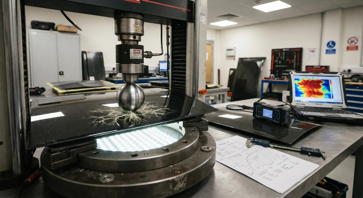
CFRP, by contrast, does not yield plastically. Instead, damage initiation in CFRP body panels under dent-type loading manifests as three distinct mechanisms:
- **Matrix microcracking** — The first damage event, occurring at local strains of 0.3–0.8% depending on the resin system. These microcracks are typically not visible to the naked eye and may not affect Class-A surface quality.
- **Delamination** — Interply separation driven by Mode II (in-plane shear) or Mode I (opening) fracture. Delaminations reduce local bending stiffness by 40–70% and can produce visible surface read-through, even if the outer ply remains intact.
- **Fiber breakage** — The ultimate failure mode, occurring at local strains of 1.2–1.8% in standard modulus fibers and 0.8–1.2% in intermediate modulus fibers. Visible fiber breakage on the painted surface is typically 0.5–2.0 mm in diameter and may appear as a localized whitening (due to matrix cracking) followed by fiber splitting.
The key engineering insight is that CFRP's dent resistance cannot be directly compared to metals on a like-for-like basis. Instead, designers must evaluate dent resistance through the lens of visible damage threshold—the load or energy level at which a Class-A surface becomes cosmetically unacceptable—which depends on panel stiffness, paint adhesion, and the strain-to-failure of the surface layers.
Table 2: Comparative Dent Resistance of Automotive Body Panel Materials
| Property | Mild Steel (DC04) | Bake-Hardened Steel (BH180) | Aluminum 6016-T4 | Al 5182-O | CFRP (Standard Modulus, 2×2 Twill, Epoxy) | CFRP (IM, UD Tape, Epoxy) |
| Typical thickness (mm) | 0.75 | 0.70 | 1.20 | 1.30 | 1.20 | 0.90 |
| Areal density (kg/m²) | 5.88 | 5.49 | 3.24 | 3.51 | 1.92 | 1.44 |
| Flexural modulus (GPa) | 210 | 210 | 70 | 70 | 55 (quasi-isotropic) | 110 (quasi-isotropic) |
| Yield strength (MPa) | 180 | 220 | 110 | 130 | N/A (no yield) | N/A (no yield) |
| Max elastic strain (%) | 0.09 | 0.10 | 0.16 | 0.19 | 0.35 (matrix-limited) | 0.30 (matrix-limited) |
| Visible dent threshold (J) – 20 mm ball indenter | 2.8 | 3.5 | 2.2 | 2.6 | 1.8 (matrix crack onset) | 2.4 (delam onset) |
| Visible dent threshold (J) – 50 mm ball indenter | 6.5 | 8.2 | 5.0 | 5.8 | 4.0 (read-through visible) | 5.5 (read-through visible) |
| Dent depth at 10 J – 20 mm ball (mm) | 0.45 | 0.28 | 0.65 | 0.50 | N/A (back-face damage) | N/A (back-face delam) |
| Repair method | PDR / filler + repaint | PDR / filler + repaint | PDR / filler + repaint | PDR / filler + repaint | Resin injection + UV cure | Patch laminate + autoclave |
| Typical repair cost (USD) | 80–150 | 80–150 | 100–200 | 100–200 | 350–650 | 600–1,200 |
Experimental Methods for Dent Resistance Characterization
The automotive industry relies on standardized dent resistance tests to qualify body panel materials. The most relevant for CFRP-metal comparison are:
Quasi-static dent test (ISO 20442 modified for composites): A spherical indenter (typically 20 mm or 50 mm diameter) is driven into the panel at 2–5 mm/min while force and displacement are recorded. For CFRP, the critical load corresponds to the first acoustic emission event (microcracking), detected by a piezoelectric sensor attached to the panel back-face. For metals, the critical load is defined at a permanent dent depth of 0.1 mm after unloading.
Low-velocity impact dent test (SAE J2526): A 10 kg impactor with spherical or hemispherical tip is dropped from heights up to 1.0 m, delivering energies of 5–98 J. Post-impact dent depth, back-face damage area, and paint adhesion (tape pull test per ASTM D3359) are measured.
Thermal cycling + dent (OEM-specific): Panels are subjected to 10 cycles of −30°C to +80°C (2-hour dwell, 500°C/hr ramp) before indentation to capture the effect of differential thermal expansion between CFRP and paint layers. CFRP panels exhibit 15–30% reduction in visible damage threshold after thermal cycling due to residual stress accumulation at the paint-substrate interface.
Key Design Considerations for CFRP Exterior Body Panels:
- Panel stiffness-driven design, not strength: CFRP hoods, decklids, and roof panels are typically stiffness-designed. For a given panel stiffness target, CFRP thickness is 60–75% of an aluminum panel and 35–50% of a steel panel—but local dent resistance near latch zones, hinge reinforcements, and character lines often requires local pad-ups or foam-backed stiffening.
- Paint film thickness matters critically: The visible dent threshold of painted CFRP is highly dependent on paint film build. At 80–100 μm total paint thickness (typical automotive), CFRP visible damage threshold is 25–35% lower than at 140–180 μm. OEMs specifying ≤100 μm paint film for weight savings must compensate through laminate stiffening or core inclusion.
- Back-face damage is the inspection challenge: While steel dents are immediately visible on the outer surface, CFRP may suffer hidden back-face delamination with no visible front-face indication. This has led to the adoption of portable ultrasonic thickness gauges (5–10 MHz) as standard equipment in body shops handling CFRP panels.
- Repair economics favor larger panel modules: The higher repair cost of CFRP panels (USD 350–1,200 vs USD 80–200 for steel) is partially offset by CFRP's ability to form larger single-piece panels—a CFRP liftgate might replace a 5-piece steel assembly, reducing assembly line investment by 30–40% despite the per-part cost being 2.5–3.5× higher.
- Hybrid solutions are gaining traction: Several 2025–2026 production vehicles use carbon fiber over aluminum sandwich constructions for closure panels, where a 0.3–0.5 mm CFRP skin is bonded onto a 0.8–1.2 mm aluminum substrate. This solution achieves 55–65% of the weight saving of full CFRP while maintaining dent resistance equivalent to 1.1 mm aluminum, at 60–70% of the cost of full CFRP.
Impact on Production Vehicle Design
The dent resistance characteristics of CFRP have directly influenced design decisions in recent production vehicles:
BMW's 7 Series (G70 generation) uses CFRP in the roof, B-pillar reinforcement, and rear shelf—areas where dent resistance is less critical—while retaining aluminum for the hood, door skins, and fenders where high dent resistance and low repair cost are prioritized. The roof panel, at 1.8 mm in a carbon/epoxy quasi-isotropic layup, passes the 20 J impact dent test with no visible front-face damage, while an aluminum panel of equivalent bending stiffness (2.8 mm) would have a visible dent depth of approximately 0.3 mm at the same impact energy.
FAQs
Q1: Can CFRP body panels be repaired using paintless dent repair (PDR) techniques?
No, conventional PDR techniques are not applicable to CFRP panels. PDR relies on the ability to plastically deform and stress-relieve the metal from the back side of the panel—a process fundamentally incompatible with CFRP's elastic-brittle behavior. Attempting PDR on a CFRP panel will cause delamination growth, matrix cracking propagation, and irreversible cosmetic damage. The only accepted repair methods for CFRP exterior panels are resin injection (for matrix cracks < 1 cm²) followed by local UV curing and refinishing, or patch laminate replacement (for larger delaminations or through-cracks), which requires scarfing, vacuum bag curing, and nondestructive inspection. These repairs must typically be performed at certified composites repair centers rather than standard body shops.
Q2: How does the dent resistance of CFRP change at elevated temperatures (summer heat, engine bay proximity)?
CFRP dent resistance degrades significantly above the resin glass transition temperature (Tg). Standard automotive-grade epoxy systems have a dry Tg of 160–200°C and a wet Tg (saturated at 85% RH) of 120–150°C. At 80°C (typical dark-painted panel temperature in summer), the matrix modulus decreases to 55–70% of the room-temperature value, reducing the visible dent threshold by 20–35%. Near-engine components must use high-Tg resin systems (BMI or phthalonitrile, 250–350°C Tg) that maintain ≥85% of room-temperature dent resistance at 150°C—but these resins increase material cost by 30–60% and require elevated-temperature cure cycles (200–250°C vs 120–180°C for standard epoxies). Carbon/phenolic systems offer even higher temperature tolerance (250°C continuous) but exhibit 20–40% lower interlaminar shear strength than epoxy systems, making them unsuitable for Class-A exterior surfaces without a gel-coated or bonded thin epoxy surfacing layer.
Q3: What testing standard applies specifically to dent resistance of CFRP automotive body panels?
There is currently no single global standard specifically for CFRP automotive body panel dent resistance. The most widely adopted protocol is an adaptation of VDA 230-210 (dent resistance of steel closures) combined with ASTM D7136 (drop-weight impact of fiber-reinforced composites) and SAE J2526 (door closure dent resistance). Several OEMs—including BMW, Mercedes-Benz, and Volvo—have issued proprietary test specifications that define: (1) indenter geometry (20 mm and 50 mm spherical), (2) impact energy levels (2 J, 5 J, 10 J for thin-gauge CFRP; 5 J, 10 J, 20 J for thick-gauge), (3) temperature conditioning (−30°C, 23°C, 80°C), (4) acceptance criteria (maximum back-face damage area of 100 mm² measured by ultrasonic C-scan after impact, and zero visible front-face damage at 0.5 m viewing distance under D65 illumination), and (5) paint adhesion qualification (cross-hatch tape pull after impact per ISO 2409, acceptable rating of GT1 or better). A unified ISO standard for CFRP automotive dent resistance is under development with an expected publication date of 2028.
Sources: BMW G70 Body Engineering Report 2024, VDA 230-210, ASTM D7136/D7136M-20, SAE J2526-2023, ISO 2409:2020, OEM proprietary test specifications for CFRP closures (BMW GS 97003-2, Mercedes-Benz DBL 5431, Volvo VCS 5001,18).
Part of topic
Related Articles
- Bio-Based Carbon Fiber Precursors: Lignin and Polyethylene for Low-Cost Production
- Large-Tow Carbon Fiber Cost Analysis: 48K vs 60K Price-Performance Comparison
- Carbon Fiber-Resin Interface Bonding: Surface Treatment and Coupling Agent Optimization
- Digital Twin for Carbon Fiber Manufacturing: Real-Time Process Monitoring and Defect Prevention
- Thermoplastic Carbon Fiber Welding for Automotive: Ultrasonic and Induction Welding Process Windows
- Large-Tow Carbon Fiber Wet Spinning: Process Optimization for 48K/60K Production Efficiency
Interested in Our Products?
Contact our team for competitive pricing and technical specifications.
Get a QuoteRelated Products

Carbon fiber standard plate-3k stripe
Lightweight, ultra-rigid standard sheets for drone fuselages, robot housings, facades and structural applications.

Carbon Fiber Plate — 3K Twill T700 1.5mm
Thin 1.5mm carbon fiber plate with 3K twill weave surface. Lightweight and stiff, commonly used for covers, panels, drone bodies, and applications requiring a premium aesthetic appearance.

Square Carbon Fiber Tube — 3K Twill T700
Square cross-section carbon fiber tube manufactured with 3K twill weave for torsional strength. Preferred for structural frames, trusses, and support columns where rectangular geometry offers design flexibility.

Carbon Fiber Plate — 3K Twill T700 3.0mm
Medium-thickness 3.0mm carbon fiber plate offering significantly higher load capacity while maintaining attractive 3K twill finish. Suitable for structural brackets, reinforcement plates, and load-bearing panels.

Carbon Fiber Plate — UD Unidirectional T700
Unidirectional carbon fiber plate with all fibers oriented in a single direction for maximum strength along the fiber axis. Essential for structural reinforcements, splints, and applications where load direction is predictable.