
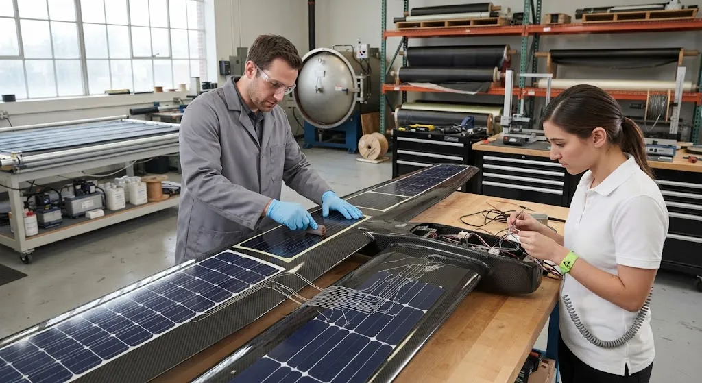
Endurance is the defining constraint of unmanned aerial vehicles (UAVs) — for surveillance, agriculture, delivery, and long-range inspection missions, every additional minute of flight time translates directly into mission capability. Lithium battery energy density has improved only inc
Introduction
Endurance is the defining constraint of unmanned aerial vehicles (UAVs) — for surveillance, agriculture, delivery, and long-range inspection missions, every additional minute of flight time translates directly into mission capability. Lithium battery energy density has improved only incrementally, and the practical ceiling for a battery-only multi-rotor is roughly 30-45 minutes. Solar integration changes that equation: for a fixed-wing drone, thin-film photovoltaic cells bonded to the wing surface can replenish energy continuously during daylight flight, extending endurance to several hours or even days for high-altitude platforms. The challenge is that adding solar cells adds mass, and mass is the enemy of a carbon fiber airframe.
This article examines how engineers reconcile these two demands — integrating photovoltaic cells while maintaining the structural efficiency that carbon fiber composites provide. We cover the structural role of the airframe, the mass budget for solar integration, wing design for photovoltaic mounting, thermal and electrical integration, and the manufacturing and certification considerations that determine whether such a platform is commercially viable.
The Structural Role of the Carbon Fiber Airframe
Carbon fiber composites dominate high-performance UAV airframes because they offer the highest strength-to-weight and stiffness-to-weight ratios of any practical structural material. For a solar-integrated drone, this structural efficiency is doubly valuable: every gram saved on the airframe can be redirected to the solar array, the battery, or the payload. The airframe serves three load-bearing roles that interact directly with the solar installation:
- Wing structure: The wing is both the primary lift surface and the substrate for most of the photovoltaic array. A carbon fiber wing skin with an upper surface optimized for solar mounting must carry bending and torsion loads while providing a stable, low-deflection platform for the cells.
- Fuselage and spar structure: The central fuselage and main spar transfer wing loads to the battery and avionics bay, and must be stiff enough that solar cells on the wing do not experience fatigue-inducing flexure.
- Thermal management structure: Carbon's low coefficient of thermal expansion and good thermal conductivity help manage the temperature of directly insolated cells, reducing efficiency loss on hot days.
The design intent is a synergy in which the wing skin is simultaneously the load-bearing structure and the mounting substrate for the photovoltaic layer, avoiding the mass penalty of a separate solar frame.
The Mass Budget and the Solar Endurance Trade-off
The fundamental engineering trade-off is a mass balance. Adding solar hardware adds mass, which increases the power required to fly, which partially offsets the energy the array collects. The net endurance gain depends on how the mass budget is allocated:
| Component | Typical Mass Contribution | Design Consideration |
|---|---|---|
| Thin-film solar cells (e.g., CIGS or flexible Si) | 1.5-3.0 kg/m² | Flexible films conform to wing curvature; rigid cells are more efficient but heavier |
| Encapsulation and adhesive layer | 0.3-0.6 kg/m² | Protects cells, bonds them to the wing skin; must not delaminate under flight loads |
| MPPT charge controller and wiring | 150-400 g total | Maximum power point tracking maximizes harvest under partial shading |
| Battery (as payload offset) | variable | Solar reduces required battery mass for a given endurance target |
| Carbon fiber airframe (wing skin) | 0.8-1.5 kg/m² | Thin skin saves mass but must resist deflection to protect the cells |
A well-integrated solar wing on a 5-8 kg fixed-wing drone typically adds 1.5-2.5 kg of total solar hardware. The endurance gain is strongly mission-dependent: for a loitering surveillance mission flown through midday, solar can extend endurance by 40-100% or more, while for short-range missions the added mass can actually reduce performance because the array never fully charges the battery.
Wing Design for Photovoltaic Mounting
The wing is where solar integration is won or lost. Key design decisions include the mounting surface area, the aerodynamic implications of a smooth upper surface, and the structural support for the cells:
- Coverage area: The usable solar area is typically 60-80% of the planform upper surface, limited by the leading edge, control surfaces, and the requirement to keep the cells within a low-strain region of the skin.
- Surface flatness and curvature: Gridded back-contact cells tolerate moderate curvature, but rapid contour changes create local stress concentrations that crack cells or encapsulant. Carbon fiber skins are laid up to provide a stable, predictable upper surface.
- Strain-limitation: Crystalline silicon cells crack at strains above roughly 400-1,000 microstrain. The wing skin and spar are designed to keep the solar zone within this limit under gust and maneuver loads, which often stiffens the wing beyond what pure aerodynamics require.
- Aerodynamic smoothness: A flush-mounted array preserves laminar flow and minimizes drag; raised frames and connectors create parasitic drag that erodes the endurance gain.
The structural consequence is that the wing is often stiffness-driven rather than strength-driven. Engineers size the laminate to control deflection and strain in the solar zone, which means slightly heavier carbon fiber skins in exchange for reliable long-term cell performance.
Thermal and Electrical Integration
Solar cells operate at maximum efficiency near 25°C, and their output falls as temperature rises. On a dark carbon fiber skin, cells in direct sunlight can reach 60-80°C, potentially cutting output by 15-30% and accelerating encapsulant degradation. Carbon fiber's high thermal conductivity helps spread and dissipate this heat, while the integrated design must also route power from cells to the charge controller and battery:
- Interconnect layout: Cells are typically connected in series strings, monitored by a maximum power point tracker that compensates for partial shading of one wing shadowed by another.
- Bus routing: Thin, flexible interconnects are routed through the wing structure to the fuselage, with strain-relief where they cross moving control surfaces.
- Charge management: An MPPT controller manages the varying voltage of the array, preventing overcharge and protecting the lithium battery during variable sunlight.
The electrical integration is comparatively straightforward; the engineering challenge is mechanical — keeping lightweight wiring and interconnects reliable through thousands of duty cycles of vibration, thermal expansion, and occasional hard landings.
Manufacturing and Certification Considerations
Manufacturing a solar-integrated carbon fiber wing requires coordinating two traditionally separate supply chains: composite fabrication and photovoltaics. Practical approaches include:
- Co-curing or post-bonding: Cells can be laminated into the outer surface during the vacuum-bag cure, or bonded with a structural adhesive film after the skin is cured. Bonding after cure is more forgiving and allows cell replacement.
- Repair access: Because a crashed or fatigued cell is costly to replace, the integration method should allow individual cell removal without damage to the structural skin.
- Environmental qualification: The integrated wing must pass thermal cycling, UV exposure, vibration, and humidity testing comparable to those for the base airframe, since the solar layer becomes part of the wing's outer surface.
- Reliability budget: A single cracked cell dropping a series string can disable a large fraction of the output, so designers balance series string length against fault tolerance.
For commercial platforms, the certification path follows the same airworthiness and operational approvals as the base airframe, with the added requirement that the solar integration not compromise load paths or create thermal hazards. The manufacturing complexity and test burden are the primary reasons solar-integrated UAVs remain specialized rather than commodity products.
Frequently Asked Questions
How much does solar integration extend drone endurance in practice?
The gain is highly mission-dependent. A fixed-wing UAV with a well-integrated array covering 1-2 m² and efficient MPPT can extend loiter endurance by 40-100% on a clear midday loiter, and high-altitude long-endurance designs can fly for many hours or overnight by climbing on stored energy and gliding. However, the added mass and drag can reduce performance on short, cloudy, or low-sun missions where the array never returns its weight. The realistic planning assumption is that solar helps sustained daylight missions and is a net negative for short-range flights, so the airframe is designed around the primary mission profile rather than a generic endurance figure.
Why not just add a bigger battery instead of solar cells?
A larger battery is often simpler, but batteries are heavy and their added mass increases the power required to fly, so endurance scales sub-linearly with battery size. Solar cells convert sunlight into power with no additional fuel, which is why they dominate in long-endurance roles. The trade-off is that solar hardware weighs more per area than battery for short durations, so for missions under roughly 45-60 minutes of flight a larger battery is more weight-efficient, while beyond that threshold solar begins to win. The crossover point depends on airframe efficiency, array area, and latitude and season of operation.
Can solar cells be added to an existing carbon fiber drone?
Retrofits are possible but rarely optimal. Adding an array to an existing airframe requires bonding cells to the already-cured wing surface, re-balancing the center of gravity, and adding charge-management hardware, and the base wing may not be stiff enough to keep cells below their strain limit. A purpose-designed wing integrates the solar layer into the laminate and is sized for the added thermal and strain loads. For most operators, a retrofit is feasible only for low-risk, development platforms; production soundness comes from designing the integration in from the start.
Conclusion
Solar-integrated carbon fiber drones occupy a specific but growing niche in the UAV market. The synergy works only when the wing is designed simultaneously as a structural lift surface and a solar substrate, when the mass budget is managed tightly, and when the thermal and mechanical requirements of the cells are respected throughout the laminate and integration design. The result is a platform that can substantially extend endurance for sustained daylight missions such as agriculture, mapping, and long-range surveillance.
For UAV manufacturers and integrators, the key is a carbon fiber airframe stiffness-engineered for the solar zone and available with quality-controlled laminate consistency. Explore our carbon fiber sheets, fabrics, and prepregs for lightweight airframe construction, or contact our technical team for material selection and laminate design support for your solar UAV project.
Part of topic
Related Articles
- Bio-Based Carbon Fiber Precursors: Lignin and Polyethylene for Low-Cost Production
- Large-Tow Carbon Fiber Cost Analysis: 48K vs 60K Price-Performance Comparison
- Carbon Fiber-Resin Interface Bonding: Surface Treatment and Coupling Agent Optimization
- Digital Twin for Carbon Fiber Manufacturing: Real-Time Process Monitoring and Defect Prevention
- Thermoplastic Carbon Fiber Welding for Automotive: Ultrasonic and Induction Welding Process Windows
- Large-Tow Carbon Fiber Wet Spinning: Process Optimization for 48K/60K Production Efficiency
Interested in Our Products?
Contact our team for competitive pricing and technical specifications.
Get a QuoteRelated Products

Carbon Fiber Fishing Rod Blank
High-quality carbon fiber fishing rod blank manufactured from multiple grades of Toray carbon fiber cloth. Available in a wide range of lengths, powers, and actions for freshwater and saltwater applications. Suitable for OEM rod building.

Carbon Fiber Plate — 3K Twill T700 3.0mm
Medium-thickness 3.0mm carbon fiber plate offering significantly higher load capacity while maintaining attractive 3K twill finish. Suitable for structural brackets, reinforcement plates, and load-bearing panels.

Custom Carbon Fiber Medical Device Components
Medical-grade carbon fiber components manufactured for imaging equipment, surgical instruments, and patient support systems. Carbon fiber's radiolucency (X-ray transparency) and high strength-to-weight ratio make it ideal for CT scanner beds, wheelchair frames, surgical robot arms, and MRI-compatible accessories. Biocompatible resin systems available.

Carbon Fiber Plate — 3K Twill T700 1.5mm
Thin 1.5mm carbon fiber plate with 3K twill weave surface. Lightweight and stiff, commonly used for covers, panels, drone bodies, and applications requiring a premium aesthetic appearance.

Square Carbon Fiber Tube — 3K Twill T700
Square cross-section carbon fiber tube manufactured with 3K twill weave for torsional strength. Preferred for structural frames, trusses, and support columns where rectangular geometry offers design flexibility.