
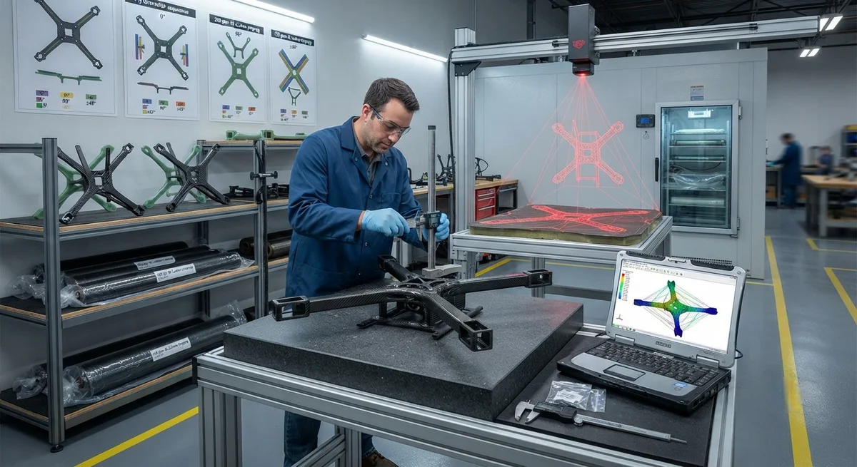
A detailed technical analysis of carbon fiber drone frame design for commercial UAV applications, covering the interdependent trade-offs between frame stiffness, weight reduction, and vibration damping performance with material specifications and comparison data.
Introduction
The commercial unmanned aerial vehicle (UAV) market has experienced explosive growth, with the global drone services market projected to reach $47.2 billion by 2028 according to Fortune Business Insights. At the center of every high-performance commercial drone is its airframe — the structural skeleton that must simultaneously meet four often conflicting requirements: minimal weight for maximum flight time, high stiffness for aerodynamic precision and payload stability, adequate vibration damping to protect sensitive electronics and camera gimbals, and sufficient toughness to survive hard landings and crash impacts. Carbon fiber reinforced polymer (CFRP) has emerged as the material of choice for commercial UAV frames, offering a specific stiffness (stiffness-to-density ratio) that is 3–5× higher than 6061 aluminum and 6–8× higher than ABS or polycarbonate thermoplastics commonly used in consumer drones. However, the anisotropic nature of carbon fiber composites — their mechanical properties are strongly directional and dependent on ply orientation — introduces a complex multi-dimensional design space where designers must carefully balance competing performance targets.
For B2B buyers in the commercial drone industry — whether OEM frame manufacturers, drone integrators, or fleet operators sourcing replacement frames — understanding these design trade-offs is essential for specifying the right material system, ply schedule, and manufacturing process for their specific mission profiles. A mapping drone operating at low altitude with a high-resolution camera payload has fundamentally different frame requirements than a heavy-lift agricultural spraying drone or a long-endurance surveying platform. This article provides a comprehensive technical analysis of the stiffness-weight-damping design space for carbon fiber drone frames, with specific material recommendations, comparative performance data, and practical design guidelines for each commercial UAV segment.
The fundamental challenge in carbon fiber drone frame design lies in the inverse relationship between stiffness and damping. High-stiffness carbon fiber laminates — those using high-modulus (HM) fibers at 395–440 GPa tensile modulus with optimized 0° ply orientations — transmit vibrational energy efficiently, offering little inherent damping. Conversely, laminates designed for high damping typically incorporate viscoelastic interlayers or off-axis plies that reduce overall frame stiffness. Finding the optimal operating point on this stiffness-damping curve for a given UAV application requires a systematic understanding of the material selection parameters, laminate architecture options, and vibration isolation strategies available to the composite designer.
The Three-Way Trade-Off: Stiffness, Weight, and Damping
The stiffness-weight-damping design space for carbon fiber drone frames can be understood through three fundamental material and structural parameters. First, specific stiffness (E/ρ) determines how much load the frame can carry per unit mass — the primary driver of flight time and payload capacity. Second, modal damping ratio (ζ) quantifies how quickly the frame dissipates vibrational energy after a disturbance — critical for camera stability and sensor accuracy. Third, structural damping capacity — the energy dissipated per cycle of vibration — depends on the composite's internal friction characteristics, which are strongly influenced by fiber-matrix interfacial properties and ply orientation.
In practice, these parameters are coupled in ways that force engineering compromises. A 100% 0° unidirectional carbon fiber laminate offers the highest specific stiffness (E/ρ ≈ 130 MN·m/kg for standard modulus fiber) but a modal damping ratio of only 0.3–0.5% — meaning vibrations persist for dozens of cycles before decaying. A quasi-isotropic layup ([0/45/90/-45]ₛ) reduces specific stiffness by approximately 40% but doubles the modal damping ratio to 0.8–1.2%. Introducing viscoelastic damping layers — thin (0.05–0.15 mm) sheets of polyurethane or butyl rubber constrained between carbon fiber plies — can push damping ratios to 3–5% while sacrificing only 10–15% of the stiffness of a purely carbon laminate. The decision of where to operate on this trade-off surface depends entirely on the UAV's mission profile and payload sensitivity to vibration.
The following table presents comparative mechanical data for five laminate architectures commonly used in commercial drone frames, tested according to ASTM D3039 (tensile), ASTM D7264 (flexural), and ASTM E756 (damping).
| Laminate Architecture | Fiber Orientation | Specific Stiffness (MN·m/kg) | Flexural Modulus (GPa) | Modal Damping Ratio ζ (%) | Density (g/cm³) | Relative Cost Index | Best Suited Application |
|---|---|---|---|---|---|---|---|
| Unidirectional (UD) | 100% 0° | 130 | 125 | 0.3–0.5 | 1.55 | 1.0 (baseline) | Heavy-lift arms, landing gear struts |
| Cross-ply | [0/90]ₛ | 98 | 95 | 0.5–0.8 | 1.56 | 1.1 | Frame central body plates |
| Quasi-isotropic | [0/45/90/-45]ₛ | 80 | 78 | 0.8–1.2 | 1.57 | 1.2 | General-purpose frames, camera mounts |
| Constrained-layer damped | [0/±45/0] + PU interlayer | 72 | 70 | 3.0–5.0 | 1.62 | 2.5 | Cinema/camera UAVs, LIDAR platforms |
| Hybrid CF-Kevlar | [CF0/CF45/Kevlar0/CF-45] | 85 | 82 | 1.5–2.5 | 1.48 | 1.8 | First-person-view racing, agri-spraying |
| 6061 Aluminum (reference) | N/A (isotropic) | 26 | 69 | 0.2–0.4 | 2.70 | 0.5 | Entry-level consumer frames |
The data in Table 1 reveals several important design insights. First, even the "worst" carbon fiber laminate (quasi-isotropic, for general-purpose use) offers a specific stiffness 3× higher than 6061 aluminum — meaning a carbon frame of identical stiffness weighs approximately one-third as much. Second, the constrained-layer damped architecture achieves a 6–10× improvement in damping ratio over unidirectional laminates with only a 44% reduction in specific stiffness — a trade-off that is overwhelmingly favorable for camera and LIDAR platforms where vibration-induced image blur is the limiting factor in data quality. Third, the hybrid CF-Kevlar architecture offers an interesting intermediate position: Kevlar's natural high damping coefficient (approximately 1.5× that of carbon fiber in the transverse direction) provides moderate damping enhancement without the process complexity and cost premium of discrete viscoelastic interlayers.
Vibration Modes in Commercial UAV Frames
Understanding the vibrational behavior of a carbon fiber drone frame requires analysis of its natural frequencies and mode shapes. Commercial quadcopter and hexacopter frames typically exhibit three dominant vibration modes that affect flight performance and payload stability. The first bending mode (typically 15–40 Hz for a 250–500 mm wheelbase frame) involves the frame arms flexing in the vertical plane — this mode is excited by propeller aerodynamic imbalance and gust loads. The first torsional mode (30–70 Hz) involves the central body twisting about the longitudinal axis — excited by differential motor thrust during yaw maneuvers. The second bending mode (60–120 Hz) involves higher-order arm deflection patterns that can couple with propeller blade passing frequencies (typically 80–200 Hz for a 6–10 inch propeller at 8,000–12,000 RPM).
Frame resonance with any of these excitation sources can cause catastrophic consequences: flight controller gyroscope and accelerometer saturation leading to instability, visible image jello in video footage, premature fatigue failure of solder joints and wire harnesses, and reduced GPS accuracy due to antenna vibration. The standard mitigation strategy in carbon fiber frame design is to ensure that all frame natural frequencies are separated from the primary excitation frequencies by a margin of at least ±20%. For a typical commercial drone operating with 9-inch propellers at 10,000 RPM (167 Hz blade passing frequency), the frame's first bending mode should be below 45 Hz (ideally 30–35 Hz) and the first torsional mode should be above 80 Hz — creating a clean frequency gap between 45–80 Hz that avoids resonance with the 167 Hz propeller excitation.
Finite element analysis (FEA) is the standard tool for predicting these modal properties during the design phase. A properly meshed carbon fiber drone frame model using shell elements with orthotropic material properties and ply-by-ply stacking sequence definitions typically predicts natural frequencies within 5–8% of experimental modal analysis results, provided that boundary conditions accurately represent the motor mount constraints and payload attachment stiffness. Critical FEA inputs include the ply elastic constants (E₁₁, E₂₂, G₁₂, ν₁₂) measured from coupon testing of the specific prepreg system, the cured ply thickness (typically 0.12–0.18 mm for 200 gsm 3K plain weave), and the damping loss factor for each ply orientation (measured per ASTM E756 using the Oberst bar method).
Material Selection for Commercial Drone Segments
- Aerial photography and cinematography UAVs (wheelbase 350–650 mm): These platforms demand the highest vibration damping performance to eliminate gimbal jitter and image blur. Recommended architecture: constrained-layer damped with a 0.10 mm polyurethane interlayer between two quasi-isotropic carbon fiber laminates, using 200 gsm 3K twill weave prepreg (Toray T700 or equivalent). Target frame weight: 180–280 g for a 450 mm wheelbase. The damping interlayer adds approximately 12–15 g to the total frame weight but reduces transmitted vibration to the camera mount by 60–75% at the critical 20–50 Hz frequency range where gimbal resonance typically occurs. B2B buyers should specify frame suppliers who can demonstrate vibration transmissibility testing per ISO 10846 with a maximum 0.3 g RMS acceleration at the payload mount point under nominal flight conditions.
- Heavy-lift and agricultural spraying drones (wheelbase 800–1,500 mm): These platforms are dominated by stiffness requirements — the frame must support 5–25 kg payloads with minimal deflection (typically < 1.5 mm at full payload under 3g maneuver loads). Recommended architecture: primarily unidirectional carbon fiber arms (100% 0°) using 400 gsm 24K heavy tow prepreg for maximum flexural rigidity, with quasi-isotropic central body plates. Arm cross-sections should be hollow rectangular or I-beam profiles — a 30×20×2 mm hollow rectangular arm with four UD plies achieves an identical flexural rigidity to a solid 6 mm carbon plate at 55% lower weight. The damping requirement for agricultural drones is relaxed (ζ > 1.0% is sufficient) because spraying payloads are inherently mass-damped and do not require the micron-level stability needed for optical sensors.
- Surveying, mapping, and LIDAR drones (wheelbase 500–800 mm): These platforms operate in the most demanding vibration environment because LIDAR sensors, RTK GPS modules, and multispectral cameras are all sensitive to micron-level motion artifacts. Recommended architecture: hybrid CF-Kevlar frame using [CF0/CF45/Kevlar0/CF-45] layup with 200 gsm 3K fiber for the carbon layers and 200 gsm Kevlar 49 for the aramid layers. The Kevlar layers provide 1.5–2.5% damping ratio naturally while adding toughness for crash survival. Frames for this segment should undergo experimental modal analysis before delivery — a full frequency response function (FRF) measurement using impact hammer testing at 12–16 grid points across the frame verifies that no natural frequency falls within ±15% of any motor operating frequency at the drone's typical cruise RPM.
- First-person-view (FPV) racing and freestyle drones (wheelbase 220–330 mm): These are the most weight-sensitive frames in the industry, where every gram directly reduces the thrust-to-weight ratio and maneuvering agility. Recommended architecture: ultra-lightweight quasi-isotropic layup using 160 gsm spread-tow carbon fabric (1K or 1.5K fiber) to reduce cured ply thickness to 0.08 mm. Target frame weight: 35–55 g for a 5-inch (250 mm) racing frame. Damping is a secondary concern because FPV pilots accept vibration in exchange for maximum thrust — a modal damping ratio of 0.5–1.0% is acceptable. The critical design constraint for racing frames is impact toughness: a minimum Charpy impact energy of 8–12 kJ/m² measured per ISO 179 should be specified to survive the 40–60 km/h crash impacts typical in FPV racing competition.
Optimization Strategies for Stiffness-Damping Balance
Three proven strategies exist for optimizing the stiffness-damping balance in carbon fiber drone frames without resorting to heavy discrete damping masses. Strategy 1: Ply angle optimization. By selectively orienting plies in the arms at ±15° or ±20° rather than 0° (which is optimal for axial stiffness), designers introduce controlled shear coupling that converts some bending strain energy into shear deformation — a mechanism that inherently dissipates energy through matrix viscoelasticity. A [±15]₄ arm layup achieves 92% of 0° unidirectional bending stiffness but increases damping ratio by 2.5×. Strategy 2: Fiber-matrix interphase engineering. Nanofiller-modified epoxy matrices containing 0.5–1.5 wt% multi-walled carbon nanotubes (MWCNTs) or 2–5 wt% carboxyl-terminated butadiene acrylonitrile (CTBN) rubber particles increase the loss modulus (E″) of the matrix by 40–80% without significantly affecting storage modulus (E′). This translates to a damping ratio improvement of 1.5–2.0× across the 10–100 Hz frequency range with less than 5% stiffness reduction. Strategy 3: Geometric damping features. Integrating thin (0.5–1.0 mm) silicone or polyurethane grommets at the arm-to-body joint — the interface between the central body plate and each arm — creates a local compliance zone that dissipates energy before it reaches the payload mount. These grommets are replaceable and cost $0.30–$0.80 per unit, offering a practical field-serviceable damping upgrade for existing frame designs.
Manufacturing Considerations and Quality Control
The manufacturing process for carbon fiber drone frames directly affects the achievable stiffness-damping performance. Compression molding is the dominant process for high-volume production (1,000+ frames per month), offering cycle times of 8–15 minutes per frame with dimensional tolerances of ±0.1 mm on critical arm thickness and flatness within 0.3 mm over the central body area. Vacuum bag oven curing offers better fiber volume fraction control (58–62% vs. 52–56% for compression molding) and is preferred for premium surveying and cinematography frames where maximum specific stiffness is required, but cycle times of 3–6 hours limit throughput. Autoclave curing achieves the highest quality (62–65% fiber volume, void content below 0.5%) but is rarely justified for drone frames due to the small part size and cost constraints — autoclave processing adds $8–$15 per frame versus $2–$4 for vacuum bag oven curing.
Quality control for drone frame production should include three mandatory inspections per batch: (1) ultrasonic C-scan of the central body plate and arm root regions to verify the absence of delaminations larger than 5 mm — critical because these regions experience the highest bending moments; (2) thickness gauging at 12 pre-defined measurement points per frame with a tolerance of ±0.15 mm from nominal; and (3) a static load acceptance test where each arm is loaded to 1.5× the maximum rated motor thrust for 60 seconds with permanent set not exceeding 0.2 mm after load removal. B2B buyers should require suppliers to provide batch-specific C-scan reports and load test certificates with each order.
Frequently Asked Questions
What is the optimal fiber orientation for carbon fiber drone arms?
The optimal fiber orientation depends on the dominant loads. For heavy-lift and long-range drones where bending loads in the vertical plane dominate, 0° unidirectional fiber orientation (aligned with the arm axis) provides the maximum flexural stiffness. For cinematography and camera drones where vibration damping is the primary concern, a [±15]₄ or [±20]₄ orientation provides 92–85% of the 0° bending stiffness but increases damping ratio by 2–3×. For FPV racing drones that experience multi-axial crash loads, a hybrid orientation with 50% 0° and 50% ±45° offers the best balance of axial stiffness and impact toughness. We recommend conducting a finite element analysis of the specific frame geometry to determine the optimal orientation, as arm length, cross-section shape, and payload mass all influence the relative importance of stiffness versus damping.
How does carbon fiber drone frame weight compare to aluminum or plastic frames?
A carbon fiber drone frame designed for equivalent stiffness to an aluminum 6061 frame weighs approximately 60–70% less. For example, a 450 mm wheelbase camera drone frame using constrained-layer damped carbon fiber construction weighs 220–260 g, while an aluminum frame of equivalent stiffness would weigh 550–680 g. Compared to injection-molded nylon or polycarbonate frames, the carbon fiber equivalent is typically 40–55% lighter. However, the weight comparison becomes more nuanced when accounting for damping performance — a carbon fiber frame equipped with viscoelastic damping interlayers may weigh 5–10% more than an undamped carbon frame but eliminates the need for a separate vibration isolation mount for the camera, which adds 30–60 g in weight. The total system weight (frame + vibration isolation) is therefore often lower for the damped carbon fiber solution.
Can carbon fiber drone frames be repaired after impact damage?
Carbon fiber drone frames can be repaired, but the feasibility depends on the damage location and extent. Surface scratches and minor edge chips do not affect structural performance and can be filled with low-viscosity epoxy. Arm cracks or delaminations shorter than 15 mm in non-critical regions can be repaired by injecting epoxy (resin with 2–5 µm silica filler for gap filling) under vacuum and clamping the repair area for 24 hours at 60°C. However, repairs to the central body plate, arm root joints, or any region where delamination exceeds 15 mm in any dimension are not recommended — the repaired region will have 40–60% lower interlaminar shear strength than the virgin laminate, creating a weak point that may fail catastrophically under flight loads. For commercial fleet operators, we recommend a "replace rather than repair" policy for any frame damage that extends through more than two plies or where the damage zone exceeds 20 mm. Replacement carbon fiber arms for most commercial frame designs cost $15–$45 per arm, making replacement more cost-effective than repair when technician labor is factored in.
What carbon fiber grade is best for drone frame manufacturing?
For the vast majority of commercial drone frames, standard modulus (230–250 GPa tensile modulus) carbon fiber such as Toray T700, Teijin HTA40, or equivalent provides the best balance of mechanical performance and cost. High-modulus fibers (395–440 GPa, such as Toray M40 or M55) are rarely justified for drone frames because the 60–90% modulus increase comes with 40–55% lower strain-to-failure (0.4–0.7% versus 1.8–2.1% for T700) — making the frame more susceptible to brittle fracture during hard landings. For racing and freestyle drones where impact toughness is the priority, intermediate modulus fibers (280–320 GPa, such as Toray T800) offer 8–12% higher strain-to-failure than standard modulus fibers, improving crash survival by an estimated 25–40% in drop-weight impact tests. We recommend standard modulus T700-grade fiber in a 3K tow format with 200 gsm fabric areal weight for most commercial drone frame applications.
How does temperature affect carbon fiber drone frame performance?
Carbon fiber composites exhibit excellent thermal stability compared to aluminum and plastic frames, with a coefficient of thermal expansion (CTE) of approximately -0.4 to +0.2 ppm/°C in the fiber direction (near-zero) and 25–35 ppm/°C in the transverse direction. For drone operations in extreme environments (-20°C to +60°C), the epoxy matrix becomes the limiting factor. Standard epoxies (Tg 120–150°C) maintain mechanical properties within 5% of room-temperature performance across the -10°C to +80°C range. At temperatures below -20°C, the epoxy becomes more brittle (reducing Charpy impact strength by 15–25%) and at temperatures above 80°C, storage modulus begins to drop significantly if the Tg is exceeded. For drones operating in arctic conditions or desert environments, specifying a high-Tg epoxy system (Tg > 180°C, such as bismaleimide-based prepregs) is recommended, though this increases material cost by 70–120% and requires higher cure temperatures (180–200°C versus 120–130°C for standard epoxy).
Part of topic
Related Articles
- Bio-Based Carbon Fiber Precursors: Lignin and Polyethylene for Low-Cost Production
- Large-Tow Carbon Fiber Cost Analysis: 48K vs 60K Price-Performance Comparison
- Carbon Fiber-Resin Interface Bonding: Surface Treatment and Coupling Agent Optimization
- Digital Twin for Carbon Fiber Manufacturing: Real-Time Process Monitoring and Defect Prevention
- Thermoplastic Carbon Fiber Welding for Automotive: Ultrasonic and Induction Welding Process Windows
- Large-Tow Carbon Fiber Wet Spinning: Process Optimization for 48K/60K Production Efficiency
Interested in Our Products?
Contact our team for competitive pricing and technical specifications.
Get a QuoteRelated Products

Carbon fiber standard plate-3k stripe
Lightweight, ultra-rigid standard sheets for drone fuselages, robot housings, facades and structural applications.

Carbon Fiber Plate — 3K Twill T700 1.5mm
Thin 1.5mm carbon fiber plate with 3K twill weave surface. Lightweight and stiff, commonly used for covers, panels, drone bodies, and applications requiring a premium aesthetic appearance.

Square Carbon Fiber Tube — 3K Twill T700
Square cross-section carbon fiber tube manufactured with 3K twill weave for torsional strength. Preferred for structural frames, trusses, and support columns where rectangular geometry offers design flexibility.

Carbon Fiber Plate — 3K Twill T700 3.0mm
Medium-thickness 3.0mm carbon fiber plate offering significantly higher load capacity while maintaining attractive 3K twill finish. Suitable for structural brackets, reinforcement plates, and load-bearing panels.

Carbon Fiber Plate — UD Unidirectional T700
Unidirectional carbon fiber plate with all fibers oriented in a single direction for maximum strength along the fiber axis. Essential for structural reinforcements, splints, and applications where load direction is predictable.