
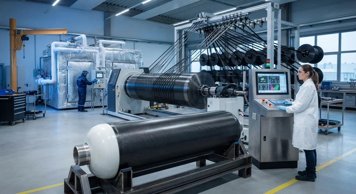
Liquid hydrogen offers the highest gravimetric energy density of any practical fuel, but storing it at −253°C places extreme demands on containment systems. Type IV tanks — a polymer liner overwrapped with carbon fiber reinforced polymer — have emerged as the leading lightweight solutio
Introduction
Liquid hydrogen offers the highest gravimetric energy density of any practical fuel, but storing it at −253°C places extreme demands on containment systems. Type IV tanks — a polymer liner overwrapped with carbon fiber reinforced polymer — have emerged as the leading lightweight solution for aerospace launch vehicles, hydrogen-powered aircraft, and heavy-duty transport applications. The carbon fiber overwrap provides the structural strength to hold cryogenic pressure, while the polymer liner prevents hydrogen permeation.
Manufacturing a reliable Type IV cryogenic tank is one of the most demanding tasks in composite engineering. The materials must survive 20 Kelvin temperature swings, thermal cycling between ambient and cryogenic temperatures, high internal pressure, and — for aerospace use — launch vibration loads. This article explains the winding parameters, material choices, and test methods that determine whether a cryogenic composite tank is fit for service, providing practical guidance for manufacturers and technical buyers.
Type IV Tank Architecture
A Type IV cryogenic hydrogen tank consists of four functional layers, each with a distinct engineering role:
- Polymer liner: A high-density polyethylene, polyamide, or polyimide liner that seals the hydrogen gas and liquid. The liner is typically rotationally molded or blow molded, with wall thickness of 3-8 mm, and must remain flexible and crack-resistant at cryogenic temperature.
- Carbon fiber overwrap: A filament-wound carbon fiber reinforced polymer layer that carries the structural loads. The overwrap provides burst strength, fatigue resistance, and dimensional stability under pressure cycling.
- Thermal insulation: A vacuum-jacketed or multilayer insulation system (MLI) that limits heat ingress. Heat leak must be controlled to below roughly 1-3 W per square meter to minimize boil-off.
- Protective outer shell: An outer jacket, typically aluminum or a second composite layer, that protects the insulation from mechanical damage and maintains the vacuum annulus.
Unlike Type III tanks (metal liner, composite overwrap), Type IV designs eliminate the metal liner entirely, reducing weight by 30-50% for the same volume. This weight advantage is decisive for aerospace and mobile applications, but it shifts the permeation and thermal management burden entirely onto the polymer liner and insulation system.
Carbon Fiber Selection for Cryogenic Service
Not all carbon fiber is suitable for cryogenic hydrogen tanks. The overwrap operates at −253°C, where matrix-dominated properties and fiber-matrix interface behavior change dramatically. Key material considerations include:
| Material Property | Requirement for Cryogenic Service | Typical Aerospace Grade | Impact |
|---|---|---|---|
| Fiber tensile strength | High to offset matrix microcracking | 4,500-6,300 MPa (T700 to T1100 class) | Burst pressure capability |
| Fiber modulus | Balanced stiffness for strain compatibility | 240-290 GPa | Prevents liner over-straining |
| Resin system | Tough, crack-resistant epoxy at 20 K | Toughened epoxy, CTE-matched | Microcrack resistance under cycling |
| Fiber areal weight | Consistent tow winding quality | 12K-24K tow, ±1% areal weight | Laminate uniformity |
| Permeability | Minimal through-thickness porosity | Void content below 1% | Hydrogen leak path control |
The most important failure mode in cryogenic composites is matrix microcracking: thermal contraction of the resin during cooldown creates tensile stresses that crack the matrix, forming paths for hydrogen permeation and reducing structural integrity. Toughened resin systems and fiber-matrix interface optimization are therefore central to cryogenic tank design. Additionally, the mismatch in thermal expansion between the carbon fiber (near-zero or slightly negative CTE) and the polymer liner must be managed through winding angle design.
Filament Winding Parameters
The filament winding process determines the structural and permeation performance of the overwrap. Four parameters dominate the outcome:
- Winding angle: Helical windings at angles of 10-30° from the axis carry axial loads; hoop windings at 85-90° carry circumferential pressure loads. Cryogenic tanks typically use a combination, with 55-60% of plies in the hoop direction for pressure vessel loading.
- Tow tension: Fiber tension during winding controls fiber volume fraction and void content. Cryogenic tank winding typically uses tensions of 10-40 N per tow, maintaining fiber volume fractions of 60-68%.
- Resin content: Lower resin content reduces thermal contraction and microcracking but risks dry fibers and voids. Target resin content for cryogenic overwraps is typically 30-38% by weight, controlled within ±2%.
- Winding path and precision: The winding path must be software-controlled to ±0.5 mm on a 2-4 meter tank, ensuring uniform coverage and no gaps or overlaps that create stress concentrations.
Curing is equally critical. Cryogenic tanks are cured under pressure in an autoclave or using heated mandrels, with cure cycles of 4-8 hours at 120-180°C. Post-cure cooling rates must be controlled to minimize residual thermal stresses, and the cured laminate must be inspected for voids using ultrasonic testing or computed tomography before insulation application.
Thermal Insulation and Boil-Off Control
Even a well-built carbon fiber overwrap cannot prevent hydrogen boil-off without effective insulation. Liquid hydrogen has a very low latent heat of vaporization — about 446 kJ/kg — so small heat leaks cause significant gas loss. Two insulation architectures dominate:
- Vacuum-jacketed tanks: An evacuated annulus between the tank wall and an outer shell reduces conduction and convection to near zero. With a vacuum of 10⁻⁴ to 10⁻⁵ mbar, boil-off rates below 1% per day are achievable.
- Multilayer insulation (MLI): Alternating layers of reflective foil and low-conductivity spacers, typically 20-60 layers, block radiative heat transfer. Combined with vacuum, MLI systems achieve effective thermal conductivities of 10⁻⁴ to 10⁻³ W/(m·K).
For aerospace applications where weight is critical, the insulation system can account for 15-25% of total tank weight, creating a design tension between boil-off control and launch mass. Modern designs also integrate cryocoolers for zero-boil-off operation on long-duration missions.
Qualification Testing for Cryogenic Tanks
Qualifying a Type IV cryogenic hydrogen tank requires a test program that validates both cryogenic performance and pressure integrity:
- Burst testing: Hydraulic burst tests to 1.5-2.5x design pressure confirm structural margin, with burst failure required to occur in the cylindrical section rather than the dome.
- Thermal cycling: Tanks must survive hundreds to thousands of cycles between ambient and −253°C without liner cracking or overwrap microcrack propagation.
- Permeation testing: Helium and hydrogen permeation rates through the liner and overwrap are measured to verify leak rates below specification limits, typically 10⁻⁶ to 10⁻⁸ mbar·L/s.
- Pressure cycling: Fatigue testing over 10,000-50,000 pressure cycles simulates refueling operations for transport applications, verifying that the overwrap retains structural integrity.
Standards such as ISO 11119-3 for composite gas cylinders and ASME Boiler and Pressure Vessel Code Case 2935 for cryogenic hydrogen tanks provide the regulatory framework, while aerospace programs add mission-specific qualification requirements.
Frequently Asked Questions
Why is carbon fiber used for cryogenic hydrogen tanks instead of steel?
Weight is the primary reason. Liquid hydrogen has very low density, so the tank structure dominates the storage system weight. A Type IV carbon fiber tank can store liquid hydrogen at a system gravimetric efficiency of 5-8% (hydrogen mass divided by total system mass), roughly double the efficiency of a steel Type I tank. For aerospace and transport applications, this weight difference determines whether hydrogen propulsion is viable at all. Carbon fiber also offers excellent fatigue resistance and does not suffer the low-temperature embrittlement that affects some steels, though the composite matrix requires careful cryogenic-grade resin selection.
What causes microcracking in cryogenic composite tanks and how is it prevented?
Microcracking is caused by thermal stresses: during cooldown to −253°C, the resin matrix contracts more than the carbon fibers, generating tensile stresses that crack the matrix. These cracks create permeation paths and reduce load transfer. Prevention strategies include using toughened resin systems with high strain-to-failure at cryogenic temperature, optimizing fiber-matrix interface adhesion, controlling void content below 1%, and designing winding architectures that distribute thermal strain. Some designs also interleave a thin crack-stopping layer or use interleaved thermoplastic films between composite plies to arrest crack propagation.
How long can liquid hydrogen be stored in a Type IV tank without significant loss?
With a high-quality vacuum-jacketed system and multilayer insulation, boil-off rates of 0.5-1% per day are achievable, meaning 99-99.5% of the hydrogen remains after one day. Over a week, losses reach roughly 4-7% without active cooling. For comparison, a poorly insulated or non-vacuum tank can lose 5-10% per day. Adding active cryocooling enables zero-boil-off storage indefinitely, which is why long-duration aerospace missions and stationary storage facilities increasingly integrate cryocoolers. The insulation quality, vacuum integrity, and tank surface-to-volume ratio are the dominant factors determining actual hold time.
Conclusion
Type IV cryogenic hydrogen tanks represent the state of the art in lightweight hydrogen storage, and their manufacturing demands discipline across material selection, filament winding, curing, and insulation. The carbon fiber overwrap is the structural backbone, but its performance at −253°C depends on every parameter from tow tension to resin toughness. For manufacturers entering this market, the path to qualification runs through rigorous thermal cycling, permeation, and burst testing against recognized standards.
For buyers evaluating cryogenic tank suppliers, the critical questions are material certification, winding process control, and demonstrated test data at cryogenic temperatures. Explore our carbon fiber products for high-performance pressure vessel applications, or contact our engineering team to discuss material selection and qualification support for your hydrogen storage program.
Part of topic
Related Articles
- Bio-Based Carbon Fiber Precursors: Lignin and Polyethylene for Low-Cost Production
- Large-Tow Carbon Fiber Cost Analysis: 48K vs 60K Price-Performance Comparison
- Carbon Fiber-Resin Interface Bonding: Surface Treatment and Coupling Agent Optimization
- Digital Twin for Carbon Fiber Manufacturing: Real-Time Process Monitoring and Defect Prevention
- Thermoplastic Carbon Fiber Welding for Automotive: Ultrasonic and Induction Welding Process Windows
- Large-Tow Carbon Fiber Wet Spinning: Process Optimization for 48K/60K Production Efficiency
Interested in Our Products?
Contact our team for competitive pricing and technical specifications.
Get a QuoteRelated Products

Carbon fiber standard plate-3k stripe
Lightweight, ultra-rigid standard sheets for drone fuselages, robot housings, facades and structural applications.

Carbon Fiber Plate — 3K Twill T700 3.0mm
Medium-thickness 3.0mm carbon fiber plate offering significantly higher load capacity while maintaining attractive 3K twill finish. Suitable for structural brackets, reinforcement plates, and load-bearing panels.

Carbon Fiber Plate — 3K Twill T700 1.5mm
Thin 1.5mm carbon fiber plate with 3K twill weave surface. Lightweight and stiff, commonly used for covers, panels, drone bodies, and applications requiring a premium aesthetic appearance.

Custom Carbon Fiber Medical Device Components
Medical-grade carbon fiber components manufactured for imaging equipment, surgical instruments, and patient support systems. Carbon fiber's radiolucency (X-ray transparency) and high strength-to-weight ratio make it ideal for CT scanner beds, wheelchair frames, surgical robot arms, and MRI-compatible accessories. Biocompatible resin systems available.

Square Carbon Fiber Tube — 3K Twill T700
Square cross-section carbon fiber tube manufactured with 3K twill weave for torsional strength. Preferred for structural frames, trusses, and support columns where rectangular geometry offers design flexibility.