
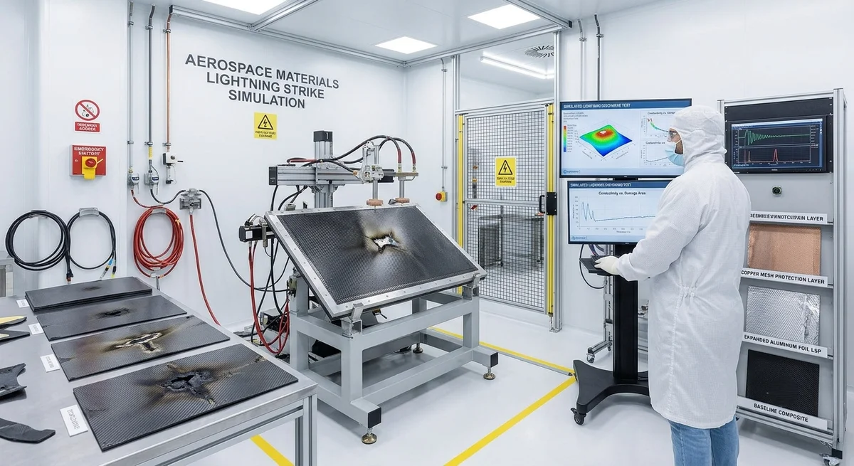
Carbon fiber has 500–1000× higher electrical resistivity than aluminum, making lightning strike protection (LSP) a critical design requirement for composite aircraft, wind turbine blades, and infrastructure. This article covers conductivity data, LSP methods (expanded foil, wire mesh, conductive paints), and certification testing per SAE ARP 5412.
The Electrical Conductivity Challenge of Carbon Fiber Composites
Carbon fiber is electrically conductive — unlike fiberglass or aramid — but its conductivity is several orders of magnitude lower than metals. The in-plane resistivity of a typical quasi-isotropic CFRP laminate is 0.1–0.5 Ω·cm (10,000–50,000 μΩ·cm), compared to 2.65 μΩ·cm for aluminum and 1.68 μΩ·cm for copper. Through-thickness resistivity is even higher: 5–50 Ω·cm due to the insulating epoxy layers between plies.
When a lightning channel (30,000–200,000 A peak current, 1–2 MV) strikes a composite structure, the high resistance leads to intense resistive heating, vaporization of the epoxy matrix, delamination, and potential structural failure. A direct strike on an unprotected CFRP panel can produce a 15–25 cm diameter damage zone with complete penetration of a 3 mm laminate — equivalent to losing 60–80% of compressive strength after impact (CAI).
This makes Lightning Strike Protection (LSP) mandatory for composite primary structures in aerospace (FAR/JAR 25.581), wind energy (IEC 61400-24), and increasingly for infrastructure applications (NFPA 780).
Electrical Conductivity of Carbon Fiber Grades
| Fiber Grade | Filament Diameter (μm) | Electrical Resistivity (μΩ·cm) | Thermal Conductivity (W/m·K) | Carbonization Temperature (°C) | Typical Application |
|---|---|---|---|---|---|
| Standard Modulus (T300) | 7.0 | 1,500–1,800 | 8–15 | 1,000–1,300 | General structural — moderate conductivity |
| Standard Modulus (T700) | 7.0 | 1,400–1,700 | 10–18 | 1,200–1,500 | Wind blades, automotive — good balance |
| Intermediate Modulus (T800) | 5.5 | 1,200–1,500 | 15–25 | 1,500–2,000 | Aerospace primary structure |
| High Modulus (M40J) | 4.6 | 800–1,100 | 40–70 | 2,000–2,500 | Space structures — high conductivity |
| Ultra-High Modulus (K13D) | 5.0 | 400–600 | 140–200 | >2,500 | Specialty — thermal management + conductivity |
| Pitch-based (K321) | 10.0 | 250–450 | 400–600 | >3,000 | Thermal management — highest conductivity |
Resistivity measured at 25°C on single filaments per ASTM D76. Note that pitch-based carbon fiber can approach aluminum-level conductivity — at 10× the cost.
Lightning Strike Protection Methods
1. Expanded Copper Foil (ECF) — Dominant Method (>80% of aerospace applications)
ECF consists of a 0.025–0.076 mm thick expanded copper foil bonded to the outer surface of the CFRP laminate, either co-cured or secondarily bonded. The expansion process creates a diamond-pattern mesh with 1–4 mm openings that weighs 50–150 g/m². Current carrying capacity: 50–200 kA depending on foil thickness and expansion ratio. Surface resistivity: 0.5–2.0 mΩ/sq. ECF adds $15–40/m² to material cost and 2–5% to laminate weight.
| ECF Grade | Thickness (mm) | Areal Weight (g/m²) | Mesh Opening (mm) | Peak Current Capacity (kA, 1 ms pulse) | Surface Resistivity (mΩ/sq) | Cost Premium ($/m²) |
|---|---|---|---|---|---|---|
| Lightweight | 0.025 | 50 | 3.0 | 50 | 2.0 | 15–20 |
| Standard | 0.038 | 78 | 2.5 | 100 | 1.2 | 20–28 |
| Heavy Duty | 0.051 | 110 | 2.0 | 150 | 0.8 | 28–35 |
| Ultra | 0.076 | 150 | 1.5 | 200 | 0.5 | 35–45 |
2. Aluminum Wire Mesh
Aluminum wire mesh (0.1–0.3 mm wire diameter, 1–4 mm mesh) offers lower cost than copper ($8–18/m²) and lighter weight (30–80 g/m²). However, aluminum is susceptible to galvanic corrosion when in direct contact with carbon fiber (galvanic potential difference: 0.6–0.9 V). A fiberglass isolation ply is required between the aluminum mesh and the carbon laminate. Aluminum mesh has lower peak current capacity — typically 40–120 kA — limiting its use to non-critical zones.
3. Conductive Paints and Coatings
Nickel-filled or silver-filled conductive paints (8–15 μm thickness, surface resistivity 0.1–1.0 Ω/sq) are used for Repair and retrofit applications where mesh integration is impractical. Durability: 3–8 years before re-coating required. Cost: $30–80/m² for application. Not certified for primary structure in aerospace but widely used for wind turbine blade leading-edge protection.
4. Interlayer CNT/Graphene Enhancement
Carbon nanotube (CNT) or graphene nanoplatelet (GNP) interlayers are an emerging technology — adding 0.5–2.0 wt% CNT to the epoxy matrix reduces through-thickness resistivity by 2–3 orders of magnitude (from 5–50 Ω·cm to 0.05–0.5 Ω·cm). Combined with a light expanded foil (50 g/m²), this meets aerospace LSP requirements while reducing total LSP system weight by 30–50%. Commercially available from Nanolab (2025) and OCSiAl (2026) at $8–15/m² additional material cost.
Certification Testing per SAE ARP 5412
Aerospace LSP systems must pass the following tests defined in SAE ARP 5412 (Aircraft Lightning Environment and Related Test Waveforms):
- Zone 1A/1B (Direct Strike Zone): Waveform A (200 kA peak, 500 kA/μs max rate of change — current return channel simulation) + Waveform B (2 kA, 5 ms — intermediate current) + Waveform C (200–800 A, 0.1–1.0 s — continuing current). Damage tolerance: No penetration beyond halfway through laminate. Residual CAI strength ≥ 70% of undamaged value per ASTM D7137.
- Zone 2A/2B (Swept Strike Zone): Waveform B + C only. Surface damage < 10 mm diameter. No fiber breakage.
- Zone 3 (Indirect Effects): Electromagnetic coupling test (H-field 40–200 A/m, E-field 10–100 kV/m). Shield effectiveness > 40 dB at 1 MHz for avionics protection.
Post-test evaluation includes: ultrasonic C-scan for delamination (tolerance: < 5 cm² per strike), visual inspection, residual mechanical testing (CAI), and electrical continuity measurement (2-point resistance across the panel must remain < 0.1 Ω).
Application-Specific Requirements
Aerospace (Commercial Aircraft): The Boeing 787 and Airbus A350 — both with >50% composite airframe by weight — use expanded copper foil as the standard LSP method. Typical areal weight: 78–110 g/m² (standard grade). Critical zones (radome, wing leading edges, tail) use heavy-duty 150 g/m² foil. Total LSP system weight for a narrow-body aircraft: 40–60 kg. Certification cost: $500,000–2,000,000 per aircraft program.
Wind Turbine Blades: IEC 61400-24 requires LSP for blades > 20 m length (essentially all commercial turbines ≥ 1 MW). Standard approach: aluminum wire mesh (0.2 mm wire, 3 mm mesh, 60 g/m²) embedded in the blade's outer gelcoat, connected to a 50–70 mm² copper down-conductor inside the blade cavity. DFARS (direct lightning attachment) receptors at blade tip. Total system cost: $2,000–8,000 per blade depending on length.
Automotive and Marine: No mandatory LSP requirements yet, but increasing adoption of CFRP body panels on EVs (Tesla Cybertruck, GM Hummer EV) has prompted NHTSA and SAE to develop recommended practices (2027 expected). Marine CFRP structures are addressed by classification society rules and typically require ECF for above-deck structures.
FAQ
Q: Why can't carbon fiber itself provide enough conductivity for lightning protection?
A: While carbon fiber filament has resistivity in the range of 500–1,800 μΩ·cm (vs 1.68 μΩ·cm for copper), the CFRP laminate's through-thickness resistivity is 5–50 Ω·cm because the epoxy matrix between plies is an electrical insulator. A 200 kA lightning strike passing through a 3 mm thick laminate with 10 Ω·cm through-thickness resistivity produces P = I²R heating of 4 × 10¹⁰ × 0.03 = 1.2 GW of peak power dissipation in the laminate. This instantaneous energy vaporizes the epoxy, delaminates the structure, and can blow a hole through the panel. An expanded copper foil with 1.2 mΩ/sq surface resistivity reduces the heating to manageable levels — approximately 5 MW of peak dissipation — which the structure can tolerate without catastrophic damage. Even the most conductive pitch-based carbon fiber (450 μΩ·cm) would still require supplementary LSP because the through-thickness conductivity remains limited by the epoxy.
Q: What is the difference between lightning Zone 1A, 1B, 2A, and 2B?
A: These zones are defined by SAE ARP 5414 and correspond to the probability and severity of lightning attachment on an aircraft: (1) Zone 1A — Initial attachment point with high probability of direct strike; requires full waveform A+B+C testing. (2) Zone 1B — Similar to 1A but with lower probability; reduced test requirements. (3) Zone 2A — Swept strike zone aft of Zone 1A; struck by lightning channel swept rearward by airflow; requires waveform B+C only. (4) Zone 2B — Swept strike zone with lower probability. On a CFRP fuselage, the critical zones requiring heaviest LSP are the nose radome (Zone 1A), wing leading edges (Zone 1A), tail cone (Zone 1B), and engine nacelles (Zone 1A/2A). The fuselage crown and belly are typically Zone 2A/2B requiring lighter LSP.
Q: Can lightning strike protection be added to existing composite structures (retrofit)?
A: Yes, but the options are limited compared to co-cured LSP during original manufacturing. The most practical retrofit methods are: (1) Bonded expanded copper foil using a film adhesive — surface preparation requires mechanical abrasion (grit-blast or sand) to expose conductive fiber, followed by cleaning and adhesive application. Bond strength: typically 15–25 MPa lap shear. (2) Conductive paint (nickel-filled epoxy, silver-filled polyurethane) — applied by spray or roller in 3–5 coats. Surface resistivity target: < 0.5 Ω/sq. (3) Aluminum flame-spray coating (> 150 μm thick) — used for wind turbine blade LSP retrofits. Expected service life of retrofit LSP: 5–10 years depending on UV exposure and mechanical abrasion. For aerospace, retrofit LSP requires full re-certification per the aircraft's original LSP specification.
Q: How does lightning strike protection affect composite repair?
A: LSP systems significantly complicate composite repair procedures. When repairing a lightning-damaged CFRP panel: (1) The damaged LSP layer (expanded foil or mesh) must be removed 25–50 mm beyond the delamination boundary, (2) The underlying CFRP is repaired using standard scarf or step-sanded prepreg repair (scarf ratio 20:1–40:1), (3) A new LSP patch is bonded over the repair area — must overlap the existing LSP by at least 25 mm to ensure electrical continuity, (4) Electrical continuity must be verified: 2-point resistance across the repair < 0.05 Ω, and (5) The repaired area must pass a 5 kV dielectric withstand test (per ASTM D149) to ensure the repair does not create a high-voltage path. Repair time: 8–24 hours for a typical 200 cm² damage zone. Repair cost: $2,000–8,000 for aerospace-grade repair. Always consult the structural repair manual (SRM) — unauthorized LSP repairs can void airframe certification.
Related Articles
- Bio-Based Carbon Fiber Precursors: Lignin and Polyethylene for Low-Cost Production
- Large-Tow Carbon Fiber Cost Analysis: 48K vs 60K Price-Performance Comparison
- Carbon Fiber-Resin Interface Bonding: Surface Treatment and Coupling Agent Optimization
- Digital Twin for Carbon Fiber Manufacturing: Real-Time Process Monitoring and Defect Prevention
- Thermoplastic Carbon Fiber Welding for Automotive: Ultrasonic and Induction Welding Process Windows
- Large-Tow Carbon Fiber Wet Spinning: Process Optimization for 48K/60K Production Efficiency
Interested in Our Products?
Contact our team for competitive pricing and technical specifications.
Get a QuoteRelated Products

Carbon fiber standard plate-3k stripe
Lightweight, ultra-rigid standard sheets for drone fuselages, robot housings, facades and structural applications.

Carbon Fiber Plate — 3K Twill T700 1.5mm
Thin 1.5mm carbon fiber plate with 3K twill weave surface. Lightweight and stiff, commonly used for covers, panels, drone bodies, and applications requiring a premium aesthetic appearance.

Square Carbon Fiber Tube — 3K Twill T700
Square cross-section carbon fiber tube manufactured with 3K twill weave for torsional strength. Preferred for structural frames, trusses, and support columns where rectangular geometry offers design flexibility.

Carbon Fiber Plate — 3K Twill T700 3.0mm
Medium-thickness 3.0mm carbon fiber plate offering significantly higher load capacity while maintaining attractive 3K twill finish. Suitable for structural brackets, reinforcement plates, and load-bearing panels.

Carbon Fiber Plate — UD Unidirectional T700
Unidirectional carbon fiber plate with all fibers oriented in a single direction for maximum strength along the fiber axis. Essential for structural reinforcements, splints, and applications where load direction is predictable.