
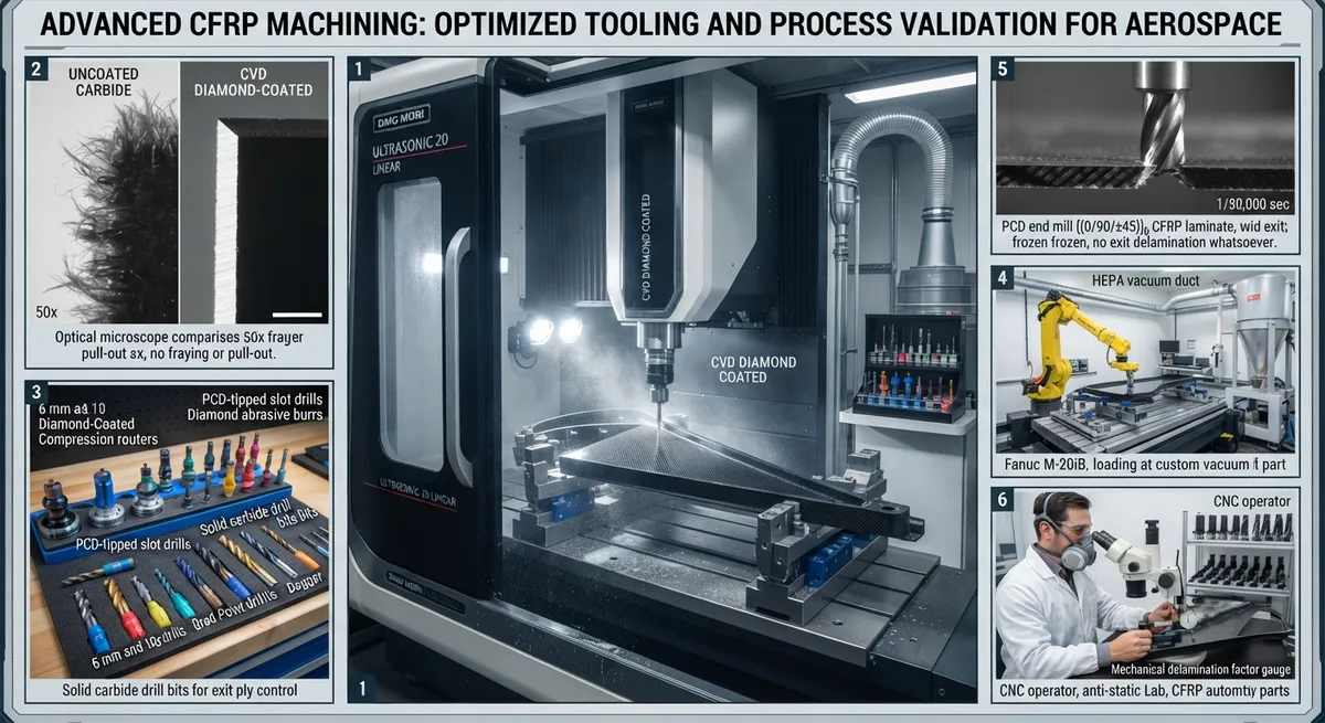
A technical guide to CNC routing and milling tool selection for carbon fiber composite machining — comparing carbide end mills, diamond-coated bits, PCD tools, and abrasive burrs for edge quality, tool life, and cost per part.
Machining carbon fiber reinforced polymer (CFRP) composites presents unique challenges that distinguish it from metal cutting. The material is highly abrasive (carbon fibers have a hardness of 7–8 on the Mohs scale, comparable to quartz), anisotropic, and prone to delamination, fiber pull-out, and thermal damage when cut with improper tool geometries or parameters. CNC routing — using computer-controlled rotating cutting tools — is the dominant method for trimming, profiling, and drilling CFRP parts in production environments ranging from aerospace to automotive to consumer goods.
Tool Material Comparison for CFRP Machining
| Tool Material | Hardness (HV) | Typical Tool Life (linear meters) | Edge Quality (delamination factor) | Cost per Tool ($) | Cost per Part ($) | Best For |
|---|---|---|---|---|---|---|
| Uncoated carbide (K10/K20) | 1,550–1,800 | 25–45 | 1.25–1.50 | $25–$45 | $0.55–$1.80 | Short runs, prototype, thin panels (<3 mm) |
| TiAlN-coated carbide | 2,300–2,800 (coating) | 40–70 | 1.20–1.40 | $35–$60 | $0.50–$1.50 | General-purpose CFRP trimming |
| CVD diamond-coated carbide | 8,000–10,000 | 150–300 | 1.05–1.15 | $80–$180 | $0.27–$1.20 | Production runs, aerospace CFRP |
| PCD (polycrystalline diamond) | 6,000–8,000 | 300–800 | 1.02–1.10 | $150–$400 | $0.19–$0.50 | High-volume, tight-tolerance, automated cells |
| Diamond abrasive burr | 8,000+ (grit) | 100–200 | 1.10–1.25 | $60–$120 | $0.30–$1.20 | Thick laminates (>6 mm), edge finishing |
Tool Geometry Parameters
Five geometry parameters critically influence CFRP routing quality:
- Flute count: 2-flute and 3-flute designs are most common for CFRP. Single-flute tools are used for very thin panels (<2 mm) to reduce cutting forces. Four-flute tools tend to clog with resin dust and generate excessive heat.
- Helix angle: Low helix angles (10–20°) produce a shearing action that reduces delamination at the top ply. High helix angles (30–45°) improve chip evacuation but create higher axial forces that can lift and delaminate the top layers. A 15° helix angle is a good starting point for general CFRP routing.
- Corner radius: Sharp corners (0.1 mm radius or less) produce cleaner edges but wear faster. A 0.5–1.0 mm corner radius extends tool life significantly for roughing passes, with a finish pass using a sharp tool for final edge quality.
- End geometry: Ball-nose ends are preferred for 3D contouring and curved surfaces. Square ends produce the best edge quality for straight trimming. For drilling, a brad-point or dagger geometry minimizes exit-ply delamination.
- Coating adhesion: For diamond-coated tools, the cobalt content of the carbide substrate must be optimized (typically 6–10% Co) to ensure adequate diamond film adhesion. Substrates with high cobalt content (>12%) cause diamond graphitization at the interface and premature coating delamination.
Cutting Parameters and Strategies
Recommended cutting parameters for CFRP routing depend on fiber orientation and laminate thickness. For a 4 mm multidirectional [(0/90/±45)]₅ laminate with CVD diamond-coated tool (6 mm diameter):
- Spindle speed: 12,000–18,000 RPM. Lower speeds risk fiber tearing; higher speeds generate excessive heat that degrades the resin matrix.
- Feed rate: 2,000–4,000 mm/min for roughing; 1,500–2,500 mm/min for finishing. Feed-per-tooth should be 0.05–0.15 mm/tooth.
- Depth of cut: Full depth (up to 12 mm in one pass) is preferred for reducing cycle time in multidirectional laminates. Step-down of 2–4 mm is used for thick panels (>12 mm) to avoid tool deflection.
- Climb vs. conventional milling: Climb milling (down-cut) produces better edge quality on the top surface but may cause burrs on the bottom. Conventional milling (up-cut) is preferred for the last 0.5 mm pass on the bottom surface to minimize exit delamination.
- Cooling: Compressed air at 4–6 bar is the standard cooling method for CFRP machining. Coolant is generally avoided — water-based coolants degrade the epoxy matrix and cause dimensional swelling; oil-based coolants create disposal and contamination issues.
Edge Quality Classification
CFRP edge quality after routing is classified by the delamination factor (F_d = maximum damaged width / nominal cut width). Industry standards define three quality levels: Class A (F_d < 1.10) — aerospace visible surfaces, requires diamond-coated or PCD tooling; Class B (F_d 1.10–1.30) — aerospace hidden surfaces and automotive structural parts; Class C (F_d > 1.30) — non-structural parts, prototyping, or subsequent edge sealing. Achieving Class A edge quality requires not only the correct tooling but also rigid fixturing, vacuum chip extraction (minimum 10 m/s air velocity at the cutting zone), and tool condition monitoring. Acoustic emission sensors or spindle load monitoring are recommended for detecting tool wear in automated production lines — a 15–20% increase in spindle load typically indicates that the diamond coating has worn through and the tool needs replacement.
Frequently Asked Questions
Can I use standard metal-cutting end mills for carbon fiber?
Standard metal-cutting end mills (4-flute, 30° helix, uncoated HSS or carbide) can be used for very short runs but will produce poor edge quality and have very short tool life. The high flute count and steep helix angle generate excessive heat (leading to resin smearing on the cut edge) and the sharp corner geometry chips rapidly against abrasive carbon fibers. For production CFRP machining, dedicated composite routing tools with diamond coating, 2-flute geometry, and 10–20° helix angles are strongly recommended. The cost premium of $40–$140 per tool is recovered in 5–20 parts through reduced tool change downtime and elimination of secondary deburring operations.
How do I reduce dust when CNC routing carbon fiber?
Carbon fiber dust is electrically conductive and a respiratory hazard — effective dust management is mandatory. The best approach combines: (1) a high-volume, high-velocity vacuum system with a HEPA filter (minimum 1,200 CFM airflow, 15–20 m/s capture velocity at the nozzle); (2) a sealed CNC enclosure with negative pressure; (3) misting systems that apply a fine water spray (50–100 mL/min) at the cutting zone to suppress airborne dust; (4) personal protective equipment including N95 or P100 respirators, safety glasses, and anti-static clothing. Many aerospace CFRP shops now use fully enclosed machining centers with automated tool changers and robotic part handling to eliminate operator exposure entirely.
What causes delamination during CFRP routing and how to prevent it?
Delamination during routing is caused primarily by excessive axial forces at the tool exit point pushing apart the bottom plies, and by heat buildup that degrades the matrix strength at the top plies. Prevention strategies include: (1) using diamond-coated or PCD tools with sharp cutting edges; (2) reducing feed rate by 30–40% on the final finishing pass; (3) using a backing board (sacrificial plywood or aluminum) beneath the workpiece; (4) optimizing fiber orientation sequencing in the layup so that the surface plies are at 0° or 90° (not ±45°, which are more prone to edge fraying); (5) employing ultrasonic-assisted routing — the high-frequency vibration (20–40 kHz) reduces cutting forces by 25–35% and virtually eliminates exit delamination. Systems such as the DMS Ultrasonic Router have demonstrated Class A edge quality on 8 mm multidirectional CFRP at feed rates of 3,000 mm/min.
Related Articles
- Bio-Based Carbon Fiber Precursors: Lignin and Polyethylene for Low-Cost Production
- Large-Tow Carbon Fiber Cost Analysis: 48K vs 60K Price-Performance Comparison
- Carbon Fiber-Resin Interface Bonding: Surface Treatment and Coupling Agent Optimization
- Digital Twin for Carbon Fiber Manufacturing: Real-Time Process Monitoring and Defect Prevention
- Thermoplastic Carbon Fiber Welding for Automotive: Ultrasonic and Induction Welding Process Windows
- Large-Tow Carbon Fiber Wet Spinning: Process Optimization for 48K/60K Production Efficiency
Interested in Our Products?
Contact our team for competitive pricing and technical specifications.
Get a QuoteRelated Products

Carbon fiber standard plate-3k stripe
Lightweight, ultra-rigid standard sheets for drone fuselages, robot housings, facades and structural applications.

Carbon Fiber Plate — 3K Twill T700 3.0mm
Medium-thickness 3.0mm carbon fiber plate offering significantly higher load capacity while maintaining attractive 3K twill finish. Suitable for structural brackets, reinforcement plates, and load-bearing panels.

Carbon Fiber Plate — 3K Twill T700 1.5mm
Thin 1.5mm carbon fiber plate with 3K twill weave surface. Lightweight and stiff, commonly used for covers, panels, drone bodies, and applications requiring a premium aesthetic appearance.

Custom Carbon Fiber Medical Device Components
Medical-grade carbon fiber components manufactured for imaging equipment, surgical instruments, and patient support systems. Carbon fiber's radiolucency (X-ray transparency) and high strength-to-weight ratio make it ideal for CT scanner beds, wheelchair frames, surgical robot arms, and MRI-compatible accessories. Biocompatible resin systems available.

Square Carbon Fiber Tube — 3K Twill T700
Square cross-section carbon fiber tube manufactured with 3K twill weave for torsional strength. Preferred for structural frames, trusses, and support columns where rectangular geometry offers design flexibility.