
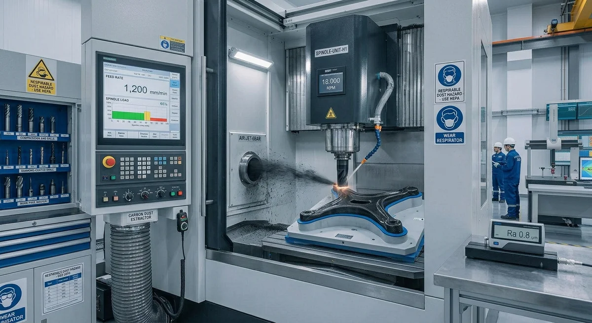
Technical guide to CNC machining of carbon fiber composites — diamond-coated tool selection, optimal feed rates, dust management, and achieving superior surface finish without delamination.
Introduction
Carbon fiber composites are increasingly used in components that require secondary machining operations — drilling holes for fasteners, trimming edges to final dimensions, milling pockets for inserts, or finishing surfaces to tight tolerances. However, the anisotropic, abrasive nature of carbon fiber makes it one of the most challenging materials to machine successfully. Poor machining parameters lead to delamination, fiber pullout, thermal degradation of the resin matrix, and rapid tool wear. This guide provides CNC programmers, shop managers, and procurement engineers with the technical data needed to optimize machining operations for carbon fiber components.
Tool Selection for Carbon Fiber Machining
Tool material and geometry are the most critical variables in carbon fiber CNC machining. Unlike metals, where carbide tools perform adequately, carbon fiber requires specialized tooling due to its high abrasiveness (carbon fibers have a hardness comparable to corundum at 9 on the Mohs scale).
| Tool Material | Hardness (HV) | Tool Life (linear meters) | Surface Finish Ra (μm) | Cost Multiplier |
|---|---|---|---|---|
| Uncoated Carbide (K10/K20) | 1,500–1,800 | 5–15 m | 2.5–5.0 | 1× (baseline) |
| TiAlN-Coated Carbide | 2,500–3,000 | 20–40 m | 1.5–3.5 | 1.5–2× |
| PCD (Polycrystalline Diamond) | 6,000–8,000 | 200–500 m | 0.5–1.2 | 8–15× |
| CVD Diamond (Thick Film) | 8,000–10,000 | 300–800 m | 0.3–0.8 | 12–20× |
Optimal Cutting Parameters
- Spindle Speed: 12,000–24,000 RPM for most operations. Higher speeds (24,000–40,000 RPM) for thin laminates (under 3 mm) to reduce cutting forces. Lower speeds (8,000–12,000 RPM) for thick cross-sections (over 10 mm) to prevent heat buildup.
- Feed Rate: 1,000–3,000 mm/min for roughing, 500–1,500 mm/min for finishing. Chip load per tooth: 0.02–0.08 mm/tooth for roughing, 0.01–0.04 mm/tooth for finishing. Feed per revolution should not exceed 0.15 mm to avoid fiber pullout.
- Depth of Cut: Axial depth: 2–8 mm for roughing, 0.2–1.0 mm for finishing. Radial depth: 30–50% of tool diameter for slotting, 10–20% for finishing. Climb milling strongly preferred to reduce delamination at the exit edge.
- Coolant Strategy: Compressed air cooling (minimum 6 bar at nozzle) is the standard method — prevents resin softening without contaminating the workpiece. Mist coolant (water-soluble oil at 5–10% concentration) for heavy roughing operations. Flood coolant NOT recommended — causes resin absorption and potential delamination.
Common Defects and Troubleshooting
- Delamination at Exit: Caused by excessive feed rate or worn tool. Solution: reduce feed by 20–30%, use backing plate (sacrificial aluminum or plywood), or apply peel ply on exit surface. Feed rate should not exceed 0.05 mm/tooth for final passes.
- Fiber Pullout / Fuzzing: Indicates dull cutting edge. Solution: replace tool immediately. For PCD tools, this occurs after 200–500 linear meters; for carbide, after 5–15 meters. Use climb milling and maintain chip load above 0.02 mm/tooth.
- Thermal Discoloration (Brown/Charred Areas): Resin thermal degradation at temperatures above 250°C. Solution: reduce spindle speed by 20%, increase feed rate by 15%, ensure air cooling reaches the cutting zone directly.
- Burr Formation on Top Layer: Caused by tool deflection. Solution: use shortest possible tool length (max overhang 3× tool diameter), use compression-style end mills that cut toward the center from both ends.
Dust Management and Safety
Carbon fiber machining produces respirable dust particles (3–10 μm diameter) that can cause skin and respiratory irritation. OSHA permissible exposure limit (PEL) for carbon fiber dust is 1 mg/m³ (respirable fraction). Required controls include: HEPA-filtered vacuum systems (minimum 99.97% efficiency at 0.3 μm), local exhaust ventilation at the machine enclosure, operators must wear N95 or P100 respirators, and anti-static clothing to prevent fiber adhesion. Annual air quality monitoring is recommended for shops machining carbon fiber more than 10 hours per week.
Frequently Asked Questions
Can standard carbide end mills be used for carbon fiber machining in a production environment?
Standard uncoated carbide end mills (K10/K20 grade) can be used for prototyping and low-volume production (under 50 parts/month), but they are not economical for production environments. Tool life of 5–15 linear meters means frequent tool changes (every 3–8 parts for typical geometries), increasing labor cost and machine downtime. For production volumes exceeding 200 parts/month, PCD tooling is strongly recommended — despite 8–15× higher tool cost, the 20–50× longer tool life results in 30–60% lower total machining cost per part.
What is the best method to prevent delamination when drilling carbon fiber?
The most effective method is using a dedicated composite drill with a brad-and-spur point geometry — the center spur engages first, preventing the drill from walking, while the sharp outer corners shear the fibers cleanly. Recommended parameters: spindle speed 6,000–12,000 RPM, feed 0.02–0.06 mm/rev. For through-holes, use a backing plate (3–6 mm aluminum or phenolic) compressed against the exit surface. For stack-ups (carbon fiber + aluminum or titanium), use variable helix drills designed for multi-material stacks, with parameters optimized for the most difficult material in the stack.
How does the surface finish of machined carbon fiber compare to as-molded surfaces?
As-molded surfaces typically achieve Ra 0.2–0.8 μm (tool-side finish) and Ra 0.8–2.5 μm (bag-side finish). Machined surfaces with proper PCD tooling and finishing parameters achieve Ra 0.5–1.2 μm, which is acceptable for most structural and cosmetic applications. However, machined edges expose fiber ends, which may require edge sealing (with epoxy or cyanoacrylate) in moisture-sensitive applications. The trade-off is that machining allows dimensional tolerances of ±0.05 mm versus ±0.2 mm for as-molded parts.
Related Articles
- Bio-Based Carbon Fiber Precursors: Lignin and Polyethylene for Low-Cost Production
- Large-Tow Carbon Fiber Cost Analysis: 48K vs 60K Price-Performance Comparison
- Carbon Fiber-Resin Interface Bonding: Surface Treatment and Coupling Agent Optimization
- Digital Twin for Carbon Fiber Manufacturing: Real-Time Process Monitoring and Defect Prevention
- Thermoplastic Carbon Fiber Welding for Automotive: Ultrasonic and Induction Welding Process Windows
- Large-Tow Carbon Fiber Wet Spinning: Process Optimization for 48K/60K Production Efficiency
Interested in Our Products?
Contact our team for competitive pricing and technical specifications.
Get a QuoteRelated Products

Carbon fiber standard plate-3k stripe
Lightweight, ultra-rigid standard sheets for drone fuselages, robot housings, facades and structural applications.

Carbon Fiber Plate — 3K Twill T700 1.5mm
Thin 1.5mm carbon fiber plate with 3K twill weave surface. Lightweight and stiff, commonly used for covers, panels, drone bodies, and applications requiring a premium aesthetic appearance.

Square Carbon Fiber Tube — 3K Twill T700
Square cross-section carbon fiber tube manufactured with 3K twill weave for torsional strength. Preferred for structural frames, trusses, and support columns where rectangular geometry offers design flexibility.

Carbon Fiber Plate — 3K Twill T700 3.0mm
Medium-thickness 3.0mm carbon fiber plate offering significantly higher load capacity while maintaining attractive 3K twill finish. Suitable for structural brackets, reinforcement plates, and load-bearing panels.

Carbon Fiber Plate — UD Unidirectional T700
Unidirectional carbon fiber plate with all fibers oriented in a single direction for maximum strength along the fiber axis. Essential for structural reinforcements, splints, and applications where load direction is predictable.