
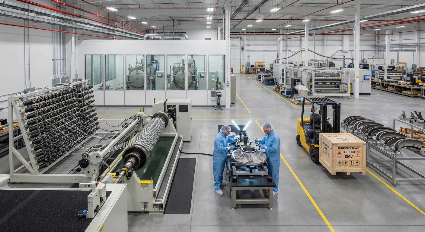
A comprehensive technical comparison between Ceramic Matrix Composites (CMC) and Carbon Fiber Reinforced Polymers (CFRP) for ultra-high temperature aerospace components. This article examines material properties, temperature limits, manufacturing costs, weight trade-offs, and application domains whe
Introduction
The aerospace industry's relentless pursuit of higher operating temperatures and lighter structures has brought two advanced composite families into direct comparison: Ceramic Matrix Composites (CMC) and Carbon Fiber Reinforced Polymers (CFRP). While CFRP has dominated lightweight structural applications for decades, the emergence of next-generation propulsion systems and hypersonic vehicles has created a thermal environment that pushes polymer matrices beyond their fundamental limits.
CMC systems, typically comprising silicon carbide (SiC) fibers embedded in a SiC or oxide ceramic matrix, offer continuous service temperatures of 1200°C to 1400°C — dramatically higher than the 180°C to 350°C range of aerospace-grade CFRP. However, this thermal capability comes with trade-offs in manufacturing complexity, cost, and specific mechanical properties that every B2B procurement team must understand before making material selection decisions.
This article provides a data-driven comparison of CMC and CFRP across seven critical parameters: temperature limits, tensile strength retention, density, manufacturing cycle time, raw material cost, repair complexity, and application maturity. We examine real production data from leading aerospace programs including the GE9X engine, the F-35 Lightning II, and next-generation hypersonic platforms.
| Property | CMC (SiC/SiC) | CFRP (IM7/8552) | Unit |
|---|---|---|---|
| Max continuous service temperature | 1200–1400 | 180–350 | °C |
| Tensile strength at RT | 300–450 | 1800–2800 | MPa |
| Tensile strength at 800°C | 280–420 | N/A (matrix decomposition) | MPa |
| Density | 2.5–3.0 | 1.5–1.6 | g/cm³ |
| Specific tensile strength (RT) | 120–180 | 1125–1867 | MPa/(g/cm³) |
| Fracture toughness (KIC) | 15–25 | 40–60 | MPa·m1/2 |
| Oxidation resistance at 1000°C | Excellent (self-passivating) | Poor (matrix burnout) | — |
| Manufacturing cycle time (per part) | 8–16 weeks | 1–4 weeks | weeks |
| Raw material cost (per kg) | $2,500–$8,000 | $50–$200 | USD |
| NDI complexity rating | High (porosity, delamination) | Moderate | 1–5 scale |
Temperature Limits and Matrix Degradation
The single most defining difference between CMC and CFRP is their respective temperature ceilings. Aerospace-grade epoxy matrices used in CFRP — such as HexPly 8552, Cycom 977-2, and CYCOM 5250-4 — begin significant property degradation above their glass transition temperatures (Tg), typically between 180°C and 230°C for standard epoxies, extending to 350°C for bismaleimide (BMI) systems. Above these temperatures, the polymer matrix undergoes chain scission, oxidation, and eventual combustion, leading to catastrophic loss of load-bearing capability.
CMC materials, by contrast, derive their matrix from ceramic precursors that are already in their fully oxidized state or are processed to form stable oxide phases. The SiC matrix in a melt-infiltrated CMC begins measurable creep only above 1200°C, while oxide-oxide CMCs can serve continuously at 1000°C to 1100°C without significant degradation. This difference of approximately 800°C to 1000°C in usable service temperature fundamentally determines the application domains for each material class.
For components in the hot section of gas turbine engines — turbine shrouds, combustor liners, nozzles — where gas path temperatures regularly exceed 1200°C, CFRP is entirely precluded. CMC has become the material of choice, with GE Aviation's LEAP engine incorporating CMC turbine shrouds that operate at 100°C to 150°C higher than comparable nickel-based superalloys while weighing one-third as much.
Manufacturing Processes and Cost Analysis
The manufacturing paradigm for CFRP — autoclave curing, resin transfer molding (RTM), or automated fiber placement (AFP) — operates at 180°C to 400°C and 3 to 10 bar pressure, with cycle times measured in hours to days. A typical aerospace CFRP fuselage panel can be laid up, cured, and inspected within a week. In contrast, CMC fabrication requires multiple high-temperature pyrolysis and infiltration cycles, each lasting 24 to 72 hours at 1000°C to 1600°C under inert atmosphere.
Chemical Vapor Infiltration (CVI), Polymer Infiltration and Pyrolysis (PIP), and Melt Infiltration (MI) are the three dominant CMC manufacturing routes. Each has distinct cost and property profiles:
- Chemical Vapor Infiltration (CVI): Produces the highest matrix purity and best high-temperature properties. Requires 4–8 infiltration cycles, each taking 24–72 hours. Fiber volume fractions reach 40–45%. Capital equipment cost exceeds $5 million per reactor. Toshiba and General Electric are the primary industrial practitioners.
- Polymer Infiltration and Pyrolysis (PIP): Lower capital cost at approximately $1–2 million per system. Requires 5–10 infiltration–pyrolysis cycles. Achieves fiber volume fractions of 35–40%. Higher residual porosity (12–18%) limits ultimate temperature capability.
- Melt Infiltration (MI): Fastest cycle — typically 2–3 infiltration steps. Produces near-net-shape components with the lowest porosity (2–5%). The silicon melt reacts with carbon to form the SiC matrix, but residual silicon limits continuous service to approximately 1200°C. GE's LEAP and GE9X CMC components use the MI process.
From a cost perspective, CFRP is approximately 30 to 100 times cheaper per kilogram of raw material than CMC. However, when evaluated on a cost-per-temperature-capability basis — that is, the cost per kilogram divided by the maximum service temperature — the gap narrows considerably. CMC at $5,000/kg providing service at 1300°C yields $3.85 per °C per kg, while CFRP at $100/kg at 250°C yields $0.40 per °C per kg. This cost-efficiency ratio becomes competitive for components where no alternative material system can operate at the required temperature.
Weight Comparison and Structural Efficiency
Specific strength and specific stiffness are the critical metrics for aerospace structures. At room temperature, CFRP offers specific tensile strengths of 1125 to 1867 MPa/(g/cm³) — approximately 6 to 10 times that of CMC. This makes CFRP overwhelmingly superior for primary and secondary airframe structures operating below 200°C, such as wing skins, fuselage barrels, and empennage components.
However, the weight comparison inverts at elevated temperatures. At 800°C, CFRP has zero residual structural capability — the polymer matrix has fully decomposed. CMC retains 80–93% of its room-temperature tensile strength at 800°C, giving it an effective specific strength that no metallic or polymer-matrix composite can approach at that temperature. For hot-section applications, the structural weight of CMC is typically 50–70% less than the equivalent nickel-based superalloy component, while providing equivalent or better durability.
The GE9X engine, powering the Boeing 777X, provides the most compelling large-scale demonstration. Each engine incorporates approximately 35 kg of CMC components — turbine shrouds, combustor liners, and nozzle components — saving an estimated 180 kg per engine compared to superalloy equivalents. Over a twin-engine aircraft service life of 30,000 to 40,000 flight cycles, this weight saving translates to approximately 1.5 million kilograms of reduced fuel burn per aircraft.
Application Domain Boundary
The demarcation between CMC and CFRP application space is primarily governed by operating temperature, but other factors including impact resistance, moisture sensitivity, electrical conductivity, and repair infrastructure also influence material selection.
| Application | Operating Temperature | Preferred Material | Reason |
|---|---|---|---|
| Turbine shrouds | 1200–1400°C | CMC (SiC/SiC) | Temperature requirement exceeds polymer capability |
| Fan blades | 80–150°C | CFRP | Superior specific strength and fatigue resistance |
| Combustor liners | 1300–1600°C | CMC with EBC | Environmental barrier coating protects against steam oxidation |
| Fuselage skins | −55 to 80°C | CFRP | Density advantage and manufacturing cost |
| Hypersonic leading edges | 1800–2200°C | CMC (C/C or C/SiC) | Ablative cooling required above CMC limits |
| Exhaust nozzles | 600–900°C | CMC (oxide/oxide) | Balance of temperature and oxidation resistance |
| Rocket nozzle extensions | 2000–3000°C | Carbon/Carbon CMC | Ablative and radiative cooling mechanisms |
FAQ
Can CMC be repaired using the same techniques as CFRP?
No. CFRP repair methods — scarf repairs, bonded patches, and mechanical fastening — are not directly transferable to CMC. Ceramic matrix composites require specialized repair techniques such as ceramic slurry infiltration followed by localized heat treatment, or the application of pre-ceramic polymer patches that are pyrolyzed in situ. These repairs typically restore 60–80% of original strength, compared to 85–95% strength restoration achievable with CFRP scarfed repairs. The repair infrastructure for CMC is currently limited to OEM and specialized repair facilities, whereas CFRP repair is widely available at MRO stations worldwide.
What is the projected cost trajectory for CMC materials over the next decade?
Industry analysts project that CMC raw material costs will decrease by 30–50% over the next ten years, driven by increased production volumes, improved fiber manufacturing processes, and the development of lower-cost precursor routes. The CMC market is expected to grow from approximately $3.5 billion in 2024 to $8–10 billion by 2035, according to forecasts from the CompositesWorld industry report. Key drivers include adoption in land-based power generation turbines (which have less stringent weight constraints but similar temperature requirements) and expansion of CMC into commercial aircraft brake systems. However, CMC is unlikely to reach CFRP-level cost parity; fundamental raw material and processing cost differences will maintain a significant price gap.
How do CMC and CFRP compare in terms of lightning strike protection for aircraft structures?
CFRP has inherently low electrical conductivity (approximately 1000–10,000 S/m in-plane, near-zero through-thickness), requiring explicit lightning strike protection measures — typically expanded copper foil or aluminum mesh embedded in the outer ply stack. CMC, particularly SiC/SiC composites, has even lower electrical conductivity (approximately 10–100 S/m), making it unsuitable as a primary lightning conduction path without additional metallic grounding. For aircraft applications where CMC is used in non-critical lightning zones (such as engine nacelles and exhaust components), isolation from the primary current path is sufficient. For CMC used in wing or fuselage surfaces, integrated metallic protection layers are mandatory.
Conclusion
The choice between CMC and CFRP for aerospace applications is fundamentally a temperature-driven decision, with structural efficiency and cost serving as secondary discriminators within each temperature regime. For components operating below 300°C, CFRP remains the optimal choice due to its superior specific strength, lower manufacturing cost, mature repair infrastructure, and established certification basis. For components exposed to continuous temperatures above 800°C, CMC is the only advanced composite option, offering weight savings of 50–70% compared to superalloys despite significantly higher material costs.
The intermediate zone — 300°C to 800°C — represents a rapidly evolving design space where both material classes are finding specialized applications. Oxide-oxide CMCs and advanced BMI-based CFRPs are competing in this regime, with selection depending on specific mission profiles, oxidation resistance requirements, and through-life maintenance costs. For B2B procurement teams, the key takeaway is that CMC and CFRP are complementary rather than competing technologies, each serving distinct thermal domains within the aerospace platform.
As production volumes scale and manufacturing technologies mature, the cost differential between the two material families will narrow, expanding CMC adoption into applications currently served by coated superalloys. The next five to ten years will see the emergence of CMC as a standard design option for high-temperature structures, occupying a material property space that neither metals nor polymer composites can fully address.
Part of topic
Related Articles
- Bio-Based Carbon Fiber Precursors: Lignin and Polyethylene for Low-Cost Production
- Large-Tow Carbon Fiber Cost Analysis: 48K vs 60K Price-Performance Comparison
- Carbon Fiber-Resin Interface Bonding: Surface Treatment and Coupling Agent Optimization
- Digital Twin for Carbon Fiber Manufacturing: Real-Time Process Monitoring and Defect Prevention
- Thermoplastic Carbon Fiber Welding for Automotive: Ultrasonic and Induction Welding Process Windows
- Large-Tow Carbon Fiber Wet Spinning: Process Optimization for 48K/60K Production Efficiency
Interested in Our Products?
Contact our team for competitive pricing and technical specifications.
Get a QuoteRelated Products

Custom Carbon Fiber Medical Device Components
Medical-grade carbon fiber components manufactured for imaging equipment, surgical instruments, and patient support systems. Carbon fiber's radiolucency (X-ray transparency) and high strength-to-weight ratio make it ideal for CT scanner beds, wheelchair frames, surgical robot arms, and MRI-compatible accessories. Biocompatible resin systems available.

Carbon fiber standard plate-3k stripe
Lightweight, ultra-rigid standard sheets for drone fuselages, robot housings, facades and structural applications.

Square Carbon Fiber Tube — 3K Twill T700
Square cross-section carbon fiber tube manufactured with 3K twill weave for torsional strength. Preferred for structural frames, trusses, and support columns where rectangular geometry offers design flexibility.

Carbon Fiber Plate — 3K Twill T700 3.0mm
Medium-thickness 3.0mm carbon fiber plate offering significantly higher load capacity while maintaining attractive 3K twill finish. Suitable for structural brackets, reinforcement plates, and load-bearing panels.

Carbon Fiber Plate — 3K Twill T700 1.5mm
Thin 1.5mm carbon fiber plate with 3K twill weave surface. Lightweight and stiff, commonly used for covers, panels, drone bodies, and applications requiring a premium aesthetic appearance.