
Every mechanical joint in a carbon fiber structure represents a compromise. A pure adhesive bond is load-efficient and fatigue-tolerant but vulnerable to peel stress and long-term environmental degradation. A pure bolted joint resists peel and is inspectable and repairable, but concentr
Introduction
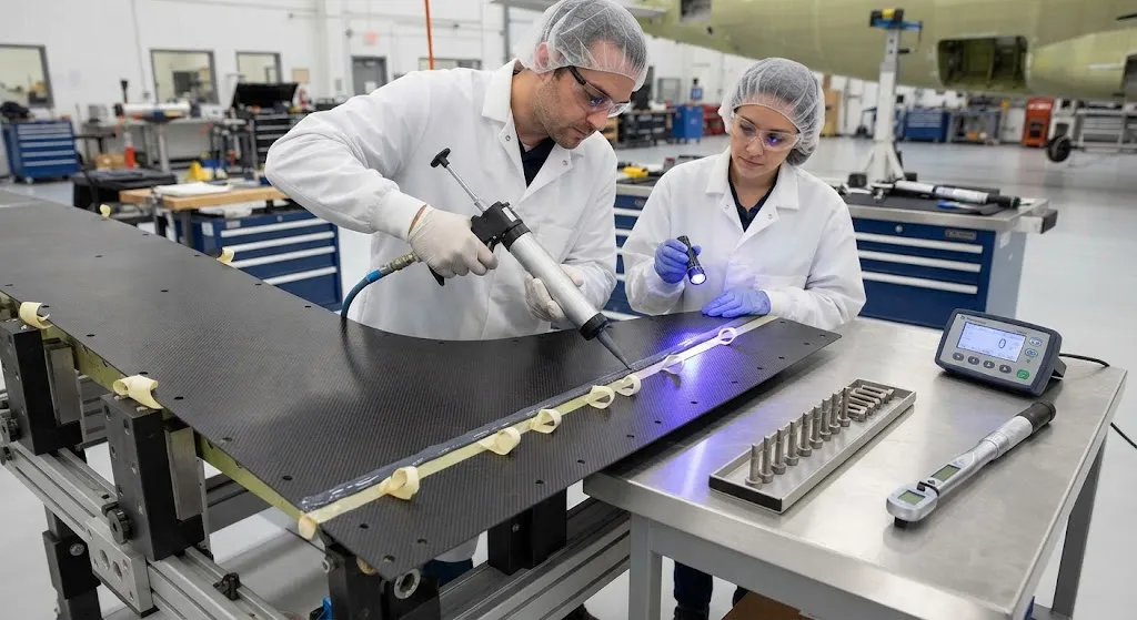
Every mechanical joint in a carbon fiber structure represents a compromise. A pure adhesive bond is load-efficient and fatigue-tolerant but vulnerable to peel stress and long-term environmental degradation. A pure bolted joint resists peel and is inspectable and repairable, but concentrates load around hole edges where carbon fiber is weakest in bearing and suffers from poor fatigue performance. The bolted-bonded hybrid joint combines both — a structural adhesive carrying the majority of load with mechanical fasteners added to protect the bond against peel and provide a fail-safe load path.
The concept is elegant in principle but demanding in practice. The two load paths share the applied load unevenly, the joint geometry generates peel stresses that neither path alone would induce, and certification authorities require evidence that the hybrid behaves predictably over decades of service including exposure to moisture and thermal cycles. This article breaks down how the hybrid joint works, quantifies the load-sharing behavior, and reviews what it takes to certify it in an aerospace context.
How the Hybrid Joint Carries Load
The defining characteristic of a bolted-bonded joint is that the adhesive and the fasteners share the applied load. At the instant of loading, the stiff adhesive layer carries almost all of the load because its low modulus distributes the transfer over a large bonded area. The bolts initially carry little. As the adhesive creeps and eventually microcracks in its most highly stressed zones, a proportion of the load transfers to the fasteners, which then carry the joint through to its ultimate failure. This staged load transfer is what makes the hybrid more damage-tolerant than either configuration alone.
The load-sharing ratio depends on the relative stiffness of the two paths, the bonded area, and the adhesive's shear strength. The table below summarizes typical behavior for a representative aerospace-grade joint:
| Joint Type | Peel Resistance | Fatigue Life | Initial Load on Bolts | Ultimate Load Path | Inspectability |
|---|---|---|---|---|---|
| Pure adhesive bond | Low | Excellent | None | Adhesive only | Limited (NDT required) |
| Pure bolted joint | High | Poor | Main path | Bolts only | Full visual |
| Bolted-bonded hybrid | High | Excellent | Low (10-30%) | Adhesive then bolts | Bolts + NDT |
Certification programs commonly assume that the bolts act as a redundant load path once the adhesive degrades beyond a threshold, so that a substantiated loss of bond does not produce an unproven, unsafe joint. This fail-safe philosophy is central to why hybrid joints are accepted in flight-critical applications that a pure bond would not satisfy.
Load Sharing and the Preload Question
One of the most studied variables in hybrid joining is the fastening preload. A high bolt preload clamps the adherends tightly together, increasing the frictional component of the load transfer and reducing the load that reaches the adhesive. This can improve static strength but complicates the fatigue picture, because a highly loaded bolt shank introduces local stress concentrations that accelerate adhesive microcracking around the hole. Conversely, a low preload leaves more load on the adhesive, improving fatigue tolerance but reducing the peel protection and fail-safe margin that motivated the hybrid in the first place.
The designer's task is to select a preload that balances three competing objectives:
- Static load capacity: Adequate clamp ensures the joint does not slip under design ultimate load and that fastener bearing stresses stay within limits.
- Fatigue tolerance: Keeping the bulk of the cyclic load on the adhesive avoids the stress concentrations that shorten bolt-dominated fatigue life.
- Peel protection: Sufficient clamp force holds the adherends together against peel, particularly at the joint ends where bending induces out-of-plane stress.
In practice the optimal preload sits in the middle of the clamp range, and designers validate it with a matrix of static and fatigue tests rather than relying on a single analytical optimum.
Peel Stresses: The Failure Mode the Bolts Are There to Catch
Adhesive joints fail prematurely when loading introduces out-of-plane (peel) stress at the bond edges. In a lap or splice joint under load, the eccentric load path induces bending that peels the adherend away from the adhesive at the joint ends. Because the adhesive is strongest in shear and weak in tension, the same structural load that the bond carries comfortably in shear can initiate a peel crack that propagates across the interface.
Bolts mitigate this by clamping the ends of the joint, suppressing the opening displacement that drives peel. The clamping force holds the adherends against the adhesive surface, converting potential peel stress into shear transferred through friction and fastener bearing. This is why the hybrid joint's peel resistance is substantially higher than a pure bond's — the fastener array provides the through-thickness constraint the adhesive lacks. Geometric measures such as scarfing the joint ends, tapering the adherends, and optimizing the bolt spacing reinforce the same effect and are routinely combined with fastening.
Environmental Degradation and Redundant Load Paths
A second reason for adding bolts is the long-term vulnerability of the adhesive to moisture and temperature. Epoxy adhesives absorb moisture over time, which plasticizes the matrix, lowers the glass transition temperature, and reduces shear strength, particularly at elevated operating temperatures. The degradation is gradual and measurable, but its magnitude varies with the service environment, making it difficult to guarantee a minimum bond strength across a twenty-year life without substantial conservatism.
The bolted-bonded configuration addresses this with redundancy. Because the fasteners provide an independent mechanical load path, the joint can be substantiated on the basis that the adhesive provides the primary fatigue-tolerant transfer while the bolts guarantee a defined minimum static strength regardless of adhesive condition. This reasoning underpins many certification approaches: demonstrate the bond's fatigue performance in pristine condition, demonstrate the bolts' static capacity independently, and show that the combined behavior remains safe across the environmental envelope.
Certification and Substantiation Practice
Certifying a hybrid joint requires more evidence than either configuration alone:
- Load-sharing characterization: Strain-gauged specimens establish how load splits between adhesive and bolts across the service load range, including any load reversal or vibration.
- Environmental tests: Coupons are conditioned at temperature and humidity extremes, then tested for static and fatigue strength to quantify bond degradation and verify the redundant bolt path still meets requirements.
- Peel and edge tests: Specimens with realistic joint geometry confirm that peel-initiated failure modes are suppressed by the fastener pattern at the critical ends.
- Damage tolerance: Tests demonstrate that if the adhesive debonds over a defined area, the bolts carry the full load with acceptable margin and no catastrophic failure.
Together these define a substantiation dossier that covers the pristine joint, the degraded joint, and the fully debonded joint — the three states a certification review expects to see addressed.
Cost and Weight Considerations
Hybrid joining is not chosen lightly because it adds both cost and weight. Fasteners, drilling, sealing, and inspection add recurring cost; the fastener array adds mass and interrupts the fiber path. The justification comes from applications where a pure bond fails on peel or certification grounds and a pure bolted joint fails on fatigue — for example, primary wing and fuselage splice joints, engine mount structure, and floor beams where a hard point must survive bond degradation. In these cases the incremental cost buys a joint that is both fatigue-tolerant and certifiable.
Frequently Asked Questions
Why not simply bond and bolt everything to be safe?
Adding bolts to every bond is not automatically safer or cheaper. Fastening adds weight, drilling interrupts the load-bearing fibers and creates stress concentrations, and the hybrid joint is more expensive to produce and to inspect. If the bolts carry too much load, the joint begins to behave like a bolted joint and loses the fatigue benefit that motivated bonding in the first place. Hybrid joining is a targeted solution for the specific joints where peel, certification, or environmental redundancy demand it, not a blanket upgrade for the whole structure.
How is load sharing measured experimentally?
Load sharing is measured with instrumented specimens that reveal the force carried by each path. Strain gauges bonded to the adherend surface and to the fastener shanks track how load enters the adhesive layer versus the fasteners at increasing applied load. More advanced techniques embed optical fiber sensors or use load cells on instrumented bolts to read the shank force directly during testing. The measurements show the characteristic staged behavior — the adhesive taking the majority initially and progressively handing load to the bolts as it degrades — which is then used to validate analytical models and the certification substantiation.
Does moisture damage the adhesive in a hybrid joint?
Yes, to a degree that must be quantified. Epoxy adhesives absorb atmospheric moisture, which plasticizes the polymer, lowers its glass transition temperature, and reduces shear and peel strength, most noticeably at elevated operating temperature. The effect is gradual and its magnitude depends on the service environment, humidity exposure, and temperature profile. That is precisely why a certified hybrid joint is substantiated for the degraded state: the environment reduces the adhesive's contribution, but the redundant bolt path is designed to carry the full load if the bond loses a defined fraction of its strength.
Conclusion
Bolted-bonded hybrid joints solve a problem neither configuration solves alone: delivering the fatigue tolerance of a bond with the peel protection and certifiable redundancy of fasteners. The load-sharing behavior is staged and must be characterized, the preload must balance static capacity, fatigue, and peel, and the environmental degradation of the adhesive is accepted because the bolts guarantee a defined minimum strength. For the right joints — primary splices, engine mounts, hard points — the incremental cost buys a joint that is both fatigue-tolerant and provable to an airworthiness authority.
For engineers evaluating hybrid joining, the practical work is a test matrix: characterize load sharing, condition coupons environmentally, and demonstrate the debonded state lands safely on the bolted path. Explore our carbon fiber laminates and structural materials for joint design work, or contact our engineering team to discuss hybrid joint testing and material qualification for your program.
Part of topic
Related Articles
- Bio-Based Carbon Fiber Precursors: Lignin and Polyethylene for Low-Cost Production
- Large-Tow Carbon Fiber Cost Analysis: 48K vs 60K Price-Performance Comparison
- Carbon Fiber-Resin Interface Bonding: Surface Treatment and Coupling Agent Optimization
- Digital Twin for Carbon Fiber Manufacturing: Real-Time Process Monitoring and Defect Prevention
- Thermoplastic Carbon Fiber Welding for Automotive: Ultrasonic and Induction Welding Process Windows
- Large-Tow Carbon Fiber Wet Spinning: Process Optimization for 48K/60K Production Efficiency
Interested in Our Products?
Contact our team for competitive pricing and technical specifications.
Get a QuoteRelated Products

Carbon Fiber Fishing Rod Blank
High-quality carbon fiber fishing rod blank manufactured from multiple grades of Toray carbon fiber cloth. Available in a wide range of lengths, powers, and actions for freshwater and saltwater applications. Suitable for OEM rod building.

Carbon Fiber Plate — 3K Twill T700 3.0mm
Medium-thickness 3.0mm carbon fiber plate offering significantly higher load capacity while maintaining attractive 3K twill finish. Suitable for structural brackets, reinforcement plates, and load-bearing panels.

Carbon Fiber Plate — UD Unidirectional T700
Unidirectional carbon fiber plate with all fibers oriented in a single direction for maximum strength along the fiber axis. Essential for structural reinforcements, splints, and applications where load direction is predictable.

Custom Carbon Fiber Medical Device Components
Medical-grade carbon fiber components manufactured for imaging equipment, surgical instruments, and patient support systems. Carbon fiber's radiolucency (X-ray transparency) and high strength-to-weight ratio make it ideal for CT scanner beds, wheelchair frames, surgical robot arms, and MRI-compatible accessories. Biocompatible resin systems available.
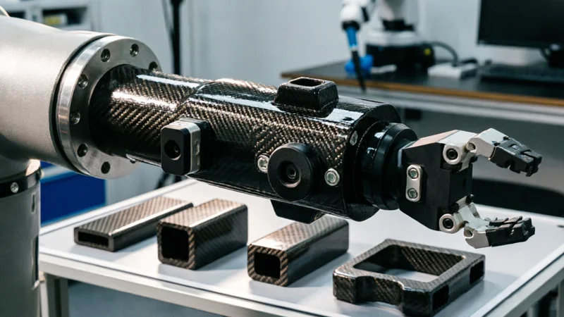
Carbon Fiber Robot End Effector Link — Custom Shape & Sensor Integration
Custom-shaped carbon fiber end effector links for robotic arms. Designed for automation integrators and research labs requiring lightweight, rigid connections between the robot wrist and gripper/tool. Can incorporate sensor mounting bosses, cable routing channels, and quick-change interfaces.