
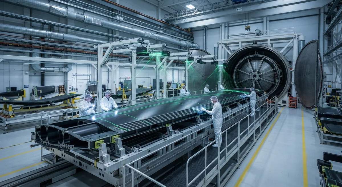
A comprehensive technical analysis of co-curing and co-bonding manufacturing techniques for carbon fiber wing spar boxes in commercial aircraft primary structures, covering process parameters, interface quality data, cost and weight comparisons, and production-scale implementation challenges.
Carbon Fiber Wing Spar Box Integration: Co-Curing and Co-Bonding Techniques for Primary Structures
The wing spar box — the primary load-bearing structure of an aircraft wing, comprising the front and rear spars, upper and lower wing skins, and chordwise ribs — represents one of the most demanding applications of carbon fiber composites in aerospace. Commercial aircraft wings must withstand ultimate loads exceeding 150% of the maximum design load, endure 60,000–90,000 pressurization cycles over a 25–30 year service life, and resist environmental exposure spanning from –55°C at cruise altitude to +80°C on tarmac. The transition from metallic to composite wing spar boxes, pioneered by Boeing with the 787 Dreamliner (2009) and followed by Airbus with the A350 XWB (2013), reduced structural weight by 15–20% while improving fatigue resistance and corrosion tolerance. However, the manufacturing integration of these large, complex structures — joining skins, spars, stringers, and ribs into a single co-cured or co-bonded assembly — remains one of the most technically challenging operations in aerospace manufacturing.
This article provides a detailed technical examination of the co-curing and co-bonding techniques used for carbon fiber wing spar box integration, with comparative analysis of process parameters, interface quality metrics, mechanical performance, and production implementation at commercial aircraft scale.
Manufacturing Integration Concepts
Three primary integration strategies exist for assembling carbon fiber wing spar box structures, each with distinct process characteristics, cost profiles, and structural performance implications:
- Co-Curing (Full Integration): All components — skins, spars, stringers, and select ribs — are assembled in the wet (uncured) state onto a single monolithic tool and cured together in one autoclave cycle. This produces a fully consolidated structure with zero secondary bond lines, eliminating the weakest link in composite assembly. However, tooling complexity is extreme, requiring matched metal tools with integrated heating and cooling channels, complex vacuum bagging strategies, and precise ply-nesting to accommodate the thickness build-ups at spar-skin intersections.
- Co-Bonding (Secondary Integration): Pre-cured subcomponents (typically spars and ribs) are assembled with uncured skins and stringers onto the same tool and cured together. The pre-cured components are surface-treated (peel ply, plasma treatment, or grit blasting) and bonded to the curing skins using film adhesive. Co-bonding reduces tooling complexity compared to full co-curing but introduces bond lines whose quality depends critically on surface preparation and adhesive selection.
- Secondary Bonding (Mechanical + Adhesive): All components are individually cured, then assembled using mechanical fasteners (titanium or Inconel bolts, Hi-Lok pins) plus adhesive faying-surface bonding. This maximizes component interchangeability and allows individual component rework, but adds substantial weight (3–5% of total wing box weight) from fasteners, introduces stress concentrations at fastener holes, and reduces the inherent fatigue advantage of composite materials.
Co-Curing Process Parameters and Performance
Full co-curing of a wing spar box typically employs the following process parameters for an epoxy-based carbon fiber prepreg system (180°C cure, such as Hexcel HexPly® 8552 or Solvay CYCOM® 977-2):
| Parameter | Typical Range | Impact on Spar Box Quality |
|---|---|---|
| Cure Temperature | 177–190°C (350–375°F) | Insufficient temperature at spar-skin junctions (<170°C) causes under-cure (Tg reduction >15°C, microcracking risk increased by 3×) |
| Cure Pressure (Autoclave) | 5.5–7.0 bar (80–100 psi) | Inadequate pressure (<5 bar) at thick sections (>15 mm) produces porosity >2%, reducing interlaminar shear strength by 20–35% |
| Dwell Time | 120–240 minutes at 177°C+ | Insufficient dwell (<90 min) at full cure temperature leaves residual cross-linking below 92%, compromising hot-wet mechanical properties |
| Heating Rate | 0.5–2.0°C/min | Rates above 3°C/min at thickness transitions create thermal gradients >40°C, inducing process-induced warpage of 5–15 mm over a 15-meter spar length |
| Vacuum Level | <30 mbar absolute (Full vacuum) | Lapses above 50 mbar during ramp allow entrapped air migration, causing planar porosity at ply drop-offs and core-skin interfaces |
| Cooling Rate | 1.0–3.0°C/min (below Tg) | Excessive cooling (>5°C/min) through the Tg region (200–150°C) generates residual tensile stress of 40–70 MPa at skin-stiffener interfaces |
The most challenging aspect of wing spar box co-curing is managing differential thermal expansion between the tool (typically Invar 36 steel, with a CTE of 1.2–1.5 ppm/°C, matched to the carbon fiber longitudinal CTE of approximately 0–1 ppm/°C) and the composite structure. With a typical wing spar box measuring 15–25 meters in length, a 1 ppm CTE mismatch produces 0.3–0.6 mm of dimensional error over the curing temperature range — sufficient to cause fit-up problems during final aircraft assembly if not accounted for in tool compensation algorithms.
Co-Bonding Surface Preparation and Interface Quality
In co-bonding, the quality of the interface between pre-cured and co-cured components determines the structural integrity of the final assembly. The bond interface must achieve an interlaminar shear strength of at least 35 MPa (for epoxy systems) and fracture toughness (G_IC) exceeding 400 J/m² to satisfy certification requirements under FAR Part 25 and EASA CS-25. Industry-standard surface preparation methods and their performance include:
| Surface Preparation Method | Shear Strength (MPa) | G_IC (J/m²) | Process Cost Factor | Scalability (parts/hr) |
|---|---|---|---|---|
| Peel Ply + Dry (Nylon, Polyester) | 35–42 | 350–500 | 1.0× (baseline) | 8–12 |
| Peel Ply + Atmospheric Plasma | 40–48 | 450–650 | 1.5–2.0× | 3–6 |
| Grit Blasting (120–220 mesh Al₂O₃) | 38–45 | 400–550 | 1.3–1.8× | 2–4 |
| Laser Ablation (UV or IR pulsed) | 42–50 | 500–700 | 2.5–4.0× | 1–2 |
| Pulsed Waterjet Ablation | 40–47 | 450–600 | 2.0–3.0× | 1–3 |
Manufacturing experience from the A350 XWB program indicates that peel ply + atmospheric plasma treatment represents the optimal balance of bond quality, process cost, and throughput for production-scale wing spar box co-bonding. Airbus uses this combination for all primary composite-to-composite bond lines on the A350 wing structure, with documented bond failure rates below 0.1% in production.
Quality Assurance and Non-Destructive Testing
Certification of co-cured and co-bonded primary composite structures requires a multi-layered NDT approach. The industry standard for wing spar box inspection combines: phased-array ultrasonic testing (PAUT) for volumetric inspection of skin and spar laminates, covering 100% of the bond-line area with 0.5–1.0 mm resolution; laser shearography for rapid large-area inspection of co-bonded interfaces, detecting disbonds as small as 5 mm diameter over a 1 m² area in under 30 seconds per scan; thermography (flash or pulsed) for co-cured sandwich structure inspection, particularly at spar-cap and rib-foot regions where thickness transitions complicate ultrasonic interpretation; and computed tomography (CT) for qualification of representative production coupons from each spar box, providing 3D void distribution, fiber orientation, and thickness data at 0.1 mm voxel resolution.
The critical acceptance criterion for primary composite wing structures is that no manufacturing-induced defect larger than 6.35 mm (0.25 inch) in its largest dimension may exist in any bond line or laminate region classified as primary structure, per Boeing D6-82552 and equivalent Airbus standards. Defects exceeding this threshold require engineering disposition — typically repair by resin injection, scarf patch, or, in rare cases, scrapping of the entire spar box section.
What is the cost difference between co-curing and co-bonding for a typical wing spar box?
For a single-aisle commercial aircraft wing spar box (approximately 15–18 meters span, 400–600 kg finished weight), co-curing typically adds 15–25% to tooling cost ($4–8 million vs $3–6 million per tool set) but reduces assembly labor by 30–40%, yielding a net direct manufacturing cost approximately 5–10% lower than co-bonding for production volumes of 40–60 shipsets per month. However, co-curing carries higher scrappage risk (5–8% vs 2–4% for co-bonding), which can offset the manufacturing cost advantage at lower production rates.
How is a co-cured wing spar box repaired in service?
Field repair of co-cured wing box structures follows a graduated approach. For minor damage (dent depth <2 mm, no visible fiber breakage), a cosmetic restoration with filler and paint suffices. For moderate damage (delamination <50 mm diameter, visible on ultrasonic but no fiber breakage), resin injection repair under vacuum pressure is certified per Boeing SRM 51-70-00 or Airbus AMM 51-20 procedures. For major damage involving fiber breakage through multiple plies, a bolted metallic doubler or composite scarf repair patch (12:1 to 30:1 scarf ratio depending on load) is bonded and bolted through the parent structure, with repair area typically limited to 5–15% of the total wing surface per zone. Co-cured structures are generally considered less repair-friendly than co-bonded or metallic equivalents due to the absence of secondary bond lines that provide natural crack-arrest features.
Conclusion
The integration of carbon fiber wing spar boxes through co-curing and co-bonding techniques represents the current state of the art in primary aerospace composite structures. Co-curing delivers the lightest, most fatigue-resistant structure by eliminating all secondary bond lines, but at the cost of extreme tooling complexity, higher scrap risk, and reduced service repairability. Co-bonding offers a pragmatic compromise — reduced integration complexity with acceptable bond line performance — and has become the preferred approach for modern commercial aircraft programs including the A350 XWB and Boeing 777X. For B2B buyers in the aerospace supply chain — including Tier 1 aerostructure manufacturers, tooling suppliers, and material suppliers — the key differentiator in successful wing spar box programs is not merely the choice of integration concept but the mastery of process control at every stage: tool compensation for CTE mismatch, precise thermal management during thick-section cure, validated surface preparation for every bond line, and comprehensive NDT coverage with quantitative acceptance criteria. As next-generation aircraft programs — including the Airbus A300-130ST Beluga successor and emerging narrow-body replacements — push toward even higher composite content, the co-curing and co-bonding technologies described here will remain central to the aerospace industry's transition to lighter, more fuel-efficient primary structures.
Part of topic
Related Articles
- Bio-Based Carbon Fiber Precursors: Lignin and Polyethylene for Low-Cost Production
- Large-Tow Carbon Fiber Cost Analysis: 48K vs 60K Price-Performance Comparison
- Carbon Fiber-Resin Interface Bonding: Surface Treatment and Coupling Agent Optimization
- Digital Twin for Carbon Fiber Manufacturing: Real-Time Process Monitoring and Defect Prevention
- Thermoplastic Carbon Fiber Welding for Automotive: Ultrasonic and Induction Welding Process Windows
- Large-Tow Carbon Fiber Wet Spinning: Process Optimization for 48K/60K Production Efficiency
Interested in Our Products?
Contact our team for competitive pricing and technical specifications.
Get a QuoteRelated Products

Carbon fiber standard plate-3k stripe
Lightweight, ultra-rigid standard sheets for drone fuselages, robot housings, facades and structural applications.

Carbon Fiber Plate — 3K Twill T700 1.5mm
Thin 1.5mm carbon fiber plate with 3K twill weave surface. Lightweight and stiff, commonly used for covers, panels, drone bodies, and applications requiring a premium aesthetic appearance.

Square Carbon Fiber Tube — 3K Twill T700
Square cross-section carbon fiber tube manufactured with 3K twill weave for torsional strength. Preferred for structural frames, trusses, and support columns where rectangular geometry offers design flexibility.

Carbon Fiber Plate — 3K Twill T700 3.0mm
Medium-thickness 3.0mm carbon fiber plate offering significantly higher load capacity while maintaining attractive 3K twill finish. Suitable for structural brackets, reinforcement plates, and load-bearing panels.

Carbon Fiber Plate — UD Unidirectional T700
Unidirectional carbon fiber plate with all fibers oriented in a single direction for maximum strength along the fiber axis. Essential for structural reinforcements, splints, and applications where load direction is predictable.