
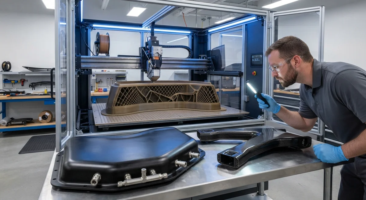
A comprehensive technical guide to using additive manufacturing (3D printing) for composite tooling — covering FDM/FFF mold fabrication, soluble mandrel printing for hollow structures, stereolithography patterns for prepreg layup, and CNC-machined trim and drill fixtures. Includes material selection (ULTEM 9085, PPSU, PC-ISO, ABS), surface preparation requirements for autoclave compatibility, thermal expansion matching strategies, and cost-benefit analysis against traditional aluminum and invar tooling across different production volumes.
Introduction: The AM Tooling Revolution in Composites Manufacturing
Additive manufacturing (AM) — commonly known as 3D printing — has emerged as a transformative technology for composite tooling, fundamentally changing how carbon fiber parts are molded, cured, and finished. Traditional composite tooling — CNC-machined aluminum, invar (nickel-iron alloy), or steel molds — carries high capital costs ($20,000-$250,000 per mold depending on size and material), long lead times (8-24 weeks), and limited design flexibility, particularly for complex internal geometries, conformal heating channels, and integrated vacuum ports. AM tooling addresses these limitations by enabling direct fabrication of complex mold geometries at 30-70% lower cost and 50-80% shorter lead times, while introducing new capabilities such as porous vacuum surfaces, topology-optimized mass reduction, and soluble mandrels for hollow composite structures that are impossible to produce with conventional tooling.
The global market for additively manufactured composite tooling was valued at approximately $480 million in 2025 and is projected to reach $1.6 billion by 2032, growing at a CAGR of 18.7% — significantly faster than the broader composite tooling market (4.2% CAGR) or the AM market overall (14.5% CAGR). This growth is driven by adoption in aerospace (Boeing, Airbus, and their Tier 1 suppliers now qualify AM tools for production), automotive (BMW i-Vertrieb and Porsche Motorsport use AM mandrels for carbon fiber intake ducts), marine (AM plug molds for hull components), and wind energy (large-format AM molds for spar cap and blade shell production). This article provides a detailed technical assessment of AM composite tooling methods, materials, design guidelines, and economic justification for B2B buyers and composites engineers evaluating this technology.
AM Tooling Categories and Methods
Four principal AM tooling categories serve the carbon fiber composites industry, each suited to specific tool types, production volumes, and thermal/mechanical requirements:
| AM Method | Typical Materials | Max Build Size (typical) | Max Service Temp (°C) | Surface Roughness Ra (μm) | Typical Tool Type | Cost vs Traditional |
|---|---|---|---|---|---|---|
| FDM/FFF (Fused Deposition) | ULTEM 9085, PPSU, PC-ISO, ABS-CF10 | 900 × 600 × 900 mm (Stratasys F900) | 150-215°C (ULTEM 9085) | 8-25 (as-printed); 2-5 (post-processed) | Layup molds, trim fixtures, drill jigs | 30-50% of Al tooling |
| SLA/DLP (Stereolithography) | Accura 60, Somos PerFORM, Loctite 3D 3843 | 500 × 500 × 400 mm | 65-120°C (high-temp resins) | 0.5-2 (as-printed) | Prepreg layup masters, patterns for silicone molds | 40-60% of Al tooling |
| MJF/Multi Jet Fusion | PA 12 + glass beads, PA 11 + CF | 380 × 284 × 380 mm (HP 5210) | 100-120°C | 5-12 (as-printed); 1-3 (vapor smoothed) | Trim fixtures, bonding tools, low-temp layup molds | 20-40% of Al tooling |
| Large-Format AM (BAAM/LAAM/robotic extrusion) | ABS-20CF, PPSU-15CF, PEI-10CF | 6,000 × 3,000 × 1,200 mm (Cincinnati BAAM) | 100-180°C | 15-50 (as-printed); 5-15 (machined) | Large plug molds, wind blade tools, hull plugs | 50-70% of Al tooling |
The selection of AM method depends primarily on three factors: (1) maximum service temperature — the tool must withstand the composite cure cycle without deformation, delamination, or excessive thermal expansion; (2) surface finish requirement — the tool surface directly affects the composite part's surface quality, particularly for Class A automotive or aerospace exterior surfaces; and (3) budget and lead time — AM tooling is most cost-effective for low-to-medium production volumes (1-500 parts) and prototype-to-production transition phases where traditional tooling lead times would delay program milestones.
Material Selection for AM Composite Tooling
The choice of AM material for composite tooling is governed by the cure cycle parameters of the composite being produced. Standard epoxy prepreg systems cure at 120-180°C (250-350°F) and 3-7 bar autoclave pressure, requiring tool materials with a heat deflection temperature (HDT) at least 20-30°C above the cure temperature. High-performance materials such as ULTEM 9085 (PEI-based, HDT 211°C at 264 psi) and PPSU (polyphenylsulfone, HDT 207°C) are the workhorses of aerospace-grade AM composite tooling. For lower-temperature cure cycles — such as polyester and vinyl ester systems curing at 25-80°C — PC-ISO (polycarbonate, HDT 138°C), PA 12 + glass bead (HDT 110°C), and ABS-20CF (HDT 105°C) provide cost-effective alternatives at 40-60% lower material cost than ULTEM.
Thermal expansion matching is a critical consideration often overlooked by first-time AM tooling adopters. The coefficient of thermal expansion (CTE) of AM tooling materials ranges from 20-60 ppm/°C (for unfilled thermoplastics) to 5-15 ppm/°C (for carbon fiber-filled grades). For comparison, carbon/epoxy composites have a near-zero CTE in the fiber direction (-0.5 to +1.0 ppm/°C for 60% FVF UD laminate) and 25-40 ppm/°C in the transverse direction. Aluminum tooling has a CTE of 23 ppm/°C, and invar has 1.2-2.0 ppm/°C. When an AM tool with a high CTE is used to cure a carbon fiber part, the differential thermal expansion during cooldown from cure temperature can induce residual stresses, warpage, and dimensional non-conformance in the composite part. The mitigation strategy involves either: (a) selecting an AM material with CTE below 15 ppm/°C (such as carbon fiber-filled PEI or PPSU grades); (b) designing the tool geometry to allow constrained thermal movement; or (c) using a hybrid tool approach where the AM material forms only the tool surface and is backed by a CTE-matched metal substructure.
- ULTEM 9085 (PEI): The most widely used AM composite tooling material. CTE 15-25 ppm/°C (unfilled), 6-12 ppm/°C (CF-filled). HDT 211°C. Autoclave proven. Compatible with standard bagging and sealant systems. Cost: $250-$400/kg (filament).
- PPSU (Polyphenylsulfone): Higher impact strength than PEI. CTE 18-28 ppm/°C (unfilled). HDT 207°C. Excellent chemical resistance to epoxy resin and MEK. Cost: $300-$500/kg.
- PC-ISO (Polycarbonate): Good for low-temp tooling. HDT 138°C. Cost: $80-$150/kg. Not suitable for autoclave cycles above 120°C.
- PA 12 + Glass Bead (HP 3D HR): For MJF tooling. HDT 110°C. Excellent surface finish (5-12 μm Ra as-printed). Cost: $60-$120/kg. Limited to low-temp cure cycles.
- ABS-20CF: Large-format AM. HDT 105°C. Cost: $40-$80/kg. Suitable for prototype and master pattern tooling only.
Surface Preparation and Vacuum Integrity
For AM tools to be used in vacuum-bagged composite curing — whether in an autoclave, oven, or vacuum-only cure — the tool surface must be vacuum-tight (leak rate below 1.0 × 10⁻³ mbar·L/s per ASTM E595) and capable of withstanding the vacuum bag sealant adhesion and release. As-printed FDM surfaces are inherently porous due to the interlayer gaps in fused deposition (typical gap width 20-100 μm between adjacent deposition roads), requiring post-processing to achieve vacuum integrity. The standard surface preparation protocol for FDM/FFF composite tools involves five steps: (1) solvent wipe with isopropyl alcohol to remove residual release agents and machining oils; (2) light sanding with 220-320 grit abrasive to level the surface and open pores; (3) application of a filled epoxy sealer (such as Huntsman Araldite CW 229/HW 229 or 3M Scotch-Weld DP270) applied in 2-3 thin coats with intermediate sanding at 400 grit; (4) high-temperature baking at 15-20°C above the maximum cure temperature for 4-8 hours to fully cure and post-cure the sealer; and (5) application of a mold release system (semi-permanent release such as Zyvax 125 or Frekote 770-NC) with 3-5 coats.
Alternative approaches to vacuum integrity include: (a) hot-pressing a thermoplastic seal film (such as PEI film 0.05-0.10 mm thick) onto the printed tool surface at 200°C and 5-10 bar — this creates a fully dense, smooth surface with Ra 1-3 μm; (b) coating with a sprayable thermoset paint system (such as Paints R-1037 tooling coating) that cures at 80-100°C; or (c) for low-temperature tools, applying a thin layer (0.2-0.5 mm) of room-temperature-cure epoxy tooling paste. Vacuum integrity testing per ASTM D5117 (pressure drop method) should be performed on every tool after surface preparation, with the acceptable leak rate being under 2.5 kPa pressure drop over 10 minutes for a tool surface area of 1 m².
Design Guidelines for AM Composite Tools
| Design Parameter | Recommendation | Rationale |
|---|---|---|
| Minimum wall thickness (FDM) | 4-6 mm (structural), 2-3 mm (non-structural) | Prevents tool deflection under autoclave pressure (3-7 bar) while minimizing print time and material cost |
| Rib/truss spacing | 80-150 mm for structural tools; topology-optimized for mass-critical tools | Supports thin walls against vacuum and pressure loads; reduces weight by 40-60% compared to solid tool |
| Draft angle | 1-3° minimum for layup tools; 0° for split-line tools | Ensures part removal without damage; AM can produce 0° draft with vacuum ejector pin integration |
| Radius at internal corners | ≥ 3 mm (FDM); ≥ 1 mm (SLA) | Avoids stress concentration points; improves tool durability through thermal cycling |
| Conformal heating channels | 5-8 mm diameter, spaced 15-25 mm apart, 2-5 mm from tool surface | Uniform heating (±3°C across tool surface); reduces cycle time by 25-40% vs conventional heating |
| Vacuum port integration | Threaded metal inserts (M6-M12) bonded into printed pockets | Metal-to-composite seal more reliable than printed threads; withstands repeated bagging cycles |
| Thermal expansion compensation | 0.3-0.8% oversize (unfilled PEI); 0.1-0.3% oversize (CF-filled PEI) | Compensates for tool CTE during cure; verified through FEA thermal simulation |
Cost-Benefit Analysis: AM vs Traditional Tooling
The economic case for AM composite tooling is strongest for low-to-medium production volumes and complex geometries. For a typical aerospace composite layup mold (600 mm × 400 mm × 150 mm deep, with integrated vacuum ports and ribbed backside), the AM approach using FDM/ULTEM 9085 costs $4,500-$7,500 and takes 3-5 weeks from design to first part, compared to $15,000-$30,000 and 10-16 weeks for CNC-machined aluminum tooling. For a single production run of 50 parts, the AM tool provides a 55-70% cost reduction per part when tooling amortization is included. For higher production volumes (500+ parts per tool), the shorter tool life of AM tools (typically 100-500 autoclave cycles for ULTEM versus 5,000-20,000 cycles for aluminum) erodes the per-part advantage, making traditional tooling more economical beyond approximately 300-800 cycles depending on tool complexity. The breakeven point shifts in favor of AM when: (a) the tool geometry is complex (internal channels, lattice backstructures, multiple split lines); (b) rapid design iterations are anticipated (engineering changes during development); (c) the part is too large for economical metal tooling; or (d) conformal heating is required for cure cycle optimization.
Case Study: AM Mandrel for Carbon Fiber Racing Intake Duct
A prominent motorsport engineering firm required a complex, organically-shaped carbon fiber intake duct for a GT3 racing car. The duct had an internal geometry with varying cross-sections (50 mm to 180 mm diameter), tight radius bends (minimum 35 mm centerline radius), and integrated mounting flanges — a geometry that was impossible to produce with a conventional multi-piece metal mandrel. The solution: a soluble AM mandrel printed in PPSU (polyphenylsulfone) on a Stratasys F900, with a wall thickness of 2.5 mm and an internal lattice for stability. The layup process: six plies of 3K plain-weave carbon fiber prepreg (200 g/m²) were laid up over the AM mandrel, vacuum-bagged, and cured at 160°C for 90 minutes. After cure, the mandrel was dissolved in a sodium hydroxide solution (10% NaOH at 80°C for 6-8 hours), leaving a pristine internal surface with zero residue. The resulting duct weighed 180 grams — 73% lighter than the aluminum equivalent — and withstood the 0.35-second pressure cycles at 4 bar intake pressure without detectable degradation after 500 hours of engine dyno testing. The AM mandrel cost was $1,200 (including print time of 38 hours on the F900) compared to an estimated $18,000 for a seven-piece CNC-machined aluminum mandrel assembly — a 93% cost reduction for the prototype run.
Frequently Asked Questions
Can 3D printed molds survive autoclave curing cycles?
Yes, provided the correct material and surface preparation are used. ULTEM 9085 and PPSU FDM tools have been validated for thousands of autoclave cycles at 160-180°C and 7 bar by major aerospace manufacturers including Boeing, Airbus, and Spirit AeroSystems. The key requirements are: (1) material HDT must exceed cure temperature by at least 20°C; (2) the tool must be sealed with an epoxy-based vacuum barrier coating; and (3) the tool design must account for CTE differential between the AM material and the composite laminate. For autoclave use, CF-filled grades (ULTEM 9085 CF10 or PPSU CF15) are preferred for their lower and more predictable CTE.
How many parts can a 3D printed composite mold produce?
Tool life depends on material, cure cycle severity, and handling: ULTEM 9085 FDM tools typically produce 100-500 parts before surface degradation requires re-surfacing. PPSU tools achieve 200-800 parts. SLA tools with high-temperature resins produce 50-200 parts. For comparison, aluminum tooling produces 5,000-20,000+ parts but at 2-4× the initial cost and 3-5× the lead time. The total cost of ownership crossover between AM and aluminum tooling occurs at approximately 300-800 parts for typical composite layup molds. For prototype and low-volume production (1-500 parts), AM tooling is almost always more economical.
What surface finish can I expect from an AM composite tool?
As-printed FDM/FFF tools have Ra 8-25 μm (depending on layer height, nozzle diameter, and contour strategy). With standard epoxy sealer post-processing (2-3 coats with intermediate sanding), the surface finish improves to Ra 1-4 μm — sufficient for most structural composite applications. For Class A surface requirements (Ra < 0.8 μm), additional polishing with 800-1200 grit abrasive and application of a high-build tooling primer is recommended. SLA tools achieve Ra 0.5-2 μm as-printed and can be polished to Ra 0.2-0.5 μm, making them suitable for prepreg layup masters and patterns for high-gloss composite parts.
What is the maximum size of a 3D printed composite tool?
For single-piece FDM tools: up to 900 × 600 × 900 mm (Stratasys F900). For SLA tools: up to 500 × 500 × 400 mm. For large-format AM (BAAM, robotic extrusion): molds up to 6,000 × 3,000 × 1,200 mm have been demonstrated. Tools larger than the printer build volume can be printed in segments and bonded together using structural epoxy adhesive (2-part paste adhesive such as 3M DP460 or Huntsman Araldite 2015) with interlocking joint geometries. Joints must be designed to withstand the autoclave pressure and temperature — scarf joints with 1:8 to 1:12 slope ratio are preferred for load-bearing tool joints.
How does the cost of AM tooling compare to traditional tooling?
For a typical 600 × 400 mm composite layup mold, FDM/ULTEM tooling costs $4,500-$7,500 (3-5 weeks lead time) versus $15,000-$30,000 (10-16 weeks) for aluminum. For complex geometries with conformal heating channels, AM delivers a 50-70% cost reduction. Tool life crossover (where total cost per part of AM equals aluminum) occurs at 300-800 parts. For prototype runs and low-volume production (1-500 parts), AM tooling delivers cost savings of 55-80% per part including tooling amortization.
Related Articles
- Bio-Based Carbon Fiber Precursors: Lignin and Polyethylene for Low-Cost Production
- Large-Tow Carbon Fiber Cost Analysis: 48K vs 60K Price-Performance Comparison
- Carbon Fiber-Resin Interface Bonding: Surface Treatment and Coupling Agent Optimization
- Digital Twin for Carbon Fiber Manufacturing: Real-Time Process Monitoring and Defect Prevention
- Thermoplastic Carbon Fiber Welding for Automotive: Ultrasonic and Induction Welding Process Windows
- Large-Tow Carbon Fiber Wet Spinning: Process Optimization for 48K/60K Production Efficiency
Interested in Our Products?
Contact our team for competitive pricing and technical specifications.
Get a QuoteRelated Products

Carbon fiber standard plate-3k stripe
Lightweight, ultra-rigid standard sheets for drone fuselages, robot housings, facades and structural applications.

Carbon Fiber Plate — 3K Twill T700 1.5mm
Thin 1.5mm carbon fiber plate with 3K twill weave surface. Lightweight and stiff, commonly used for covers, panels, drone bodies, and applications requiring a premium aesthetic appearance.

Square Carbon Fiber Tube — 3K Twill T700
Square cross-section carbon fiber tube manufactured with 3K twill weave for torsional strength. Preferred for structural frames, trusses, and support columns where rectangular geometry offers design flexibility.

Carbon Fiber Plate — 3K Twill T700 3.0mm
Medium-thickness 3.0mm carbon fiber plate offering significantly higher load capacity while maintaining attractive 3K twill finish. Suitable for structural brackets, reinforcement plates, and load-bearing panels.

Carbon Fiber Plate — UD Unidirectional T700
Unidirectional carbon fiber plate with all fibers oriented in a single direction for maximum strength along the fiber axis. Essential for structural reinforcements, splints, and applications where load direction is predictable.