
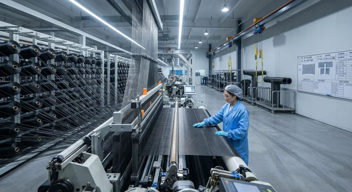
Explore how 3D woven carbon fiber preforms deliver near-net-shape reinforcement for complex geometries, eliminating interlaminar weaknesses and reducing trim waste by up to 75%. Comprehensive mechanic
Introduction to 3D Woven Carbon Fiber Preforms
The evolution of composite manufacturing has driven demand for reinforcement architectures that can accommodate complex, load-bearing geometries without sacrificing structural integrity. Traditional 2D laminate stacking — where individual plies are laid up and co-cured — introduces interlaminar weakness at ply boundaries, delamination risk, and labor-intensive hand layup cycles. 3D woven carbon fiber preforms address these limitations by integrating multiple yarn layers into a single, continuous textile structure during the weaving process itself.
A 3D woven preform is a near-net-shape textile reinforcement produced on specialized weaving looms that interlace warp, weft, and binder yarns in three orthogonal directions. Unlike 2D fabrics that must be draped, cut, and stacked, 3D preforms are woven directly to the target geometry — T-sections, Pi-joints, I-beams, curved panels, and hollow ducts — dramatically reducing trimming waste and eliminating ply nesting entirely. For procurement managers evaluating advanced reinforcement solutions, 3D weaving represents a step-change in throughput, repeatability, and damage tolerance.
Manufacturing Process and Key Technologies
Multi-Axis 3D Weaving Platforms
Modern 3D weaving machines employ Jacquard shedding mechanisms and programmable rapier insertion to control hundreds of individual binder yarns per layer. The process begins with a digital 3D model of the target preform geometry, which is sliced into weaving instructions. Carrier shuttles or pneumatic insertion systems place weft yarns across the warp sheet while binder yarns penetrate the thickness direction, locking each layer to its neighbors.
Three dominant weave architectures are used in production:
- Orthogonal 3D weave: Separate warp, weft, and binder systems produce a fully three-dimensional net structure with balanced in-plane and through-thickness properties. Preferred for thick-section structural components.
- Angle-interlock weave: Binder yarns run at an angle through the thickness, offering higher drapability and shear compliance. Suitable for doubly-curved aerospace panels.
- Layer-to-layer weave: Binders connect adjacent layers without penetrating the full thickness. Balances formability with moderate delamination resistance for automotive floor pans and seat shells.
Resin Infusion Compatibility
3D preforms are designed to interface with liquid composite molding processes — primarily vacuum-assisted resin transfer molding (VARTM) and resin transfer molding (RTM). The open architecture of the woven structure promotes uniform resin flow through the thickness, reducing void content to below 1.5% in production parts. Preform permeability can be tailored by adjusting weave density, binder tension, and tow size.
Mechanical Performance Comparison
The following table compares typical mechanical properties of 3D woven carbon fiber preforms against conventional 2D laminate stacks using the same fiber volume fraction (~55%):
| Property | 2D Laminate (Quasi-Isotropic) | 3D Orthogonal Weave | Improvement (%) |
|---|---|---|---|
| Interlaminar shear strength (ILSS) | 45 MPa | 78 MPa | +73% |
| Mode I fracture toughness (GIc) | 0.28 kJ/m² | 0.62 kJ/m² | +121% |
| Impact damage tolerance (CAI after 6.7 J/mm) | 185 MPa | 265 MPa | +43% |
| Through-thickness thermal conductivity | 0.6 W/m·K | 2.1 W/m·K | +250% |
| Trim waste per part | 25–40% | 5–10% | −75% |
| Layup labor per m² | 8–12 hours | 1.5–3 hours | −75% |
These figures demonstrate that 3D woven preforms deliver interlaminar shear strength improvements of over 70%, fracture toughness more than double that of 2D laminates, and dramatic reductions in both material waste and manufacturing labor.
Typical Applications and Industry Case Studies
Aerospace Structural Joints
Pi-joints and T-connectors fabricated from 3D woven preforms have been adopted in aircraft wing rib-to-spar attachments. The continuous through-thickness reinforcement eliminates the bonded or bolted secondary joints required in 2D laminate construction, reducing part count by up to 60% in wing box assemblies.
Automotive Crash Structures
Several European OEMs now specify 3D woven carbon fiber preforms for battery enclosure crash rails and front impact crush cones. The enhanced damage tolerance ensures that the structure absorbs energy progressively — rather than delaminating catastrophically — during high-speed collision events.
Industrial and Marine Components
For propeller blades, pump impellers, and robot arms that experience multidirectional loading, 3D woven preforms provide tailorability of fiber orientation through the thickness that cannot be achieved with biaxial or triaxial non-crimp fabrics.
FAQ: 3D Woven Carbon Fiber Preforms
What fiber types are compatible with 3D weaving?
Standard carbon fiber tows from 3K to 50K, as well as hybrid yarns (carbon/aramid, carbon/glass), can be woven. The primary constraint is yarn flexibility — very high-modulus fibers (M55J class) with less than 1.5% elongation may require modified loom tension settings or heated sizing removal prior to weaving.
What are the typical lead times for custom 3D preform tooling?
Loom setup and weave-pattern programming typically require 4–6 weeks for first-article preforms. Production rates range from 0.5 to 3 m² per hour depending on thickness and geometry complexity. For high-volume applications (>10,000 parts/year), dedicated multi-head looms can reduce cycle times by a further 40%.
Can 3D woven preforms be combined with automated fiber placement?
Yes. Hybrid preforms that combine 3D woven cores with AFP-deposited surface plies are an emerging solution for components requiring both through-thickness reinforcement and precise surface fiber steering. Several Tier 1 aerospace suppliers have qualified this hybrid approach for engine nacelle structures.
How does the cost of 3D woven preforms compare to 2D prepreg laminates?
At present, 3D woven preform raw material costs are 15–25% higher than equivalent 2D prepreg due to specialized loom investment and lower production volume. However, total part cost is often 10–20% lower because of reduced trim waste, elimination of ply cutting and nesting labor, and shorter infusion cycles. As weaving throughput increases, the cost gap is projected to close by 2028.
What quality assurance methods are used for 3D preforms?
Micro-CT scanning is the gold standard for inspecting internal fiber architecture and binder-path integrity. In-production QA relies on optical weave-pattern analysis (camera-based systems that verify yarn spacing ±0.2 mm) combined with areal weight measurement at 1 m intervals. For aerospace-grade preforms, ultrasonic C-scan of the infused panel is mandatory.
Part of topic
Related Articles
- Bio-Based Carbon Fiber Precursors: Lignin and Polyethylene for Low-Cost Production
- Large-Tow Carbon Fiber Cost Analysis: 48K vs 60K Price-Performance Comparison
- Carbon Fiber-Resin Interface Bonding: Surface Treatment and Coupling Agent Optimization
- Digital Twin for Carbon Fiber Manufacturing: Real-Time Process Monitoring and Defect Prevention
- Thermoplastic Carbon Fiber Welding for Automotive: Ultrasonic and Induction Welding Process Windows
- Large-Tow Carbon Fiber Wet Spinning: Process Optimization for 48K/60K Production Efficiency
Interested in Our Products?
Contact our team for competitive pricing and technical specifications.
Get a QuoteRelated Products

Carbon fiber standard plate-3k stripe
Lightweight, ultra-rigid standard sheets for drone fuselages, robot housings, facades and structural applications.

Carbon Fiber Plate — 3K Twill T700 1.5mm
Thin 1.5mm carbon fiber plate with 3K twill weave surface. Lightweight and stiff, commonly used for covers, panels, drone bodies, and applications requiring a premium aesthetic appearance.

Square Carbon Fiber Tube — 3K Twill T700
Square cross-section carbon fiber tube manufactured with 3K twill weave for torsional strength. Preferred for structural frames, trusses, and support columns where rectangular geometry offers design flexibility.

Carbon Fiber Plate — 3K Twill T700 3.0mm
Medium-thickness 3.0mm carbon fiber plate offering significantly higher load capacity while maintaining attractive 3K twill finish. Suitable for structural brackets, reinforcement plates, and load-bearing panels.

Carbon Fiber Plate — UD Unidirectional T700
Unidirectional carbon fiber plate with all fibers oriented in a single direction for maximum strength along the fiber axis. Essential for structural reinforcements, splints, and applications where load direction is predictable.