
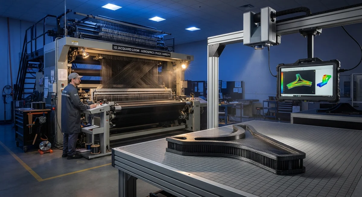
3D woven carbon fiber preforms represent one of the most significant advances in aerospace composite manufacturing in the past two decades. Conventional carbon fiber composites are built as stacked 2D laminates, where individual plies are bonded only by the resin matrix. This architectu
Introduction
3D woven carbon fiber preforms represent one of the most significant advances in aerospace composite manufacturing in the past two decades. Conventional carbon fiber composites are built as stacked 2D laminates, where individual plies are bonded only by the resin matrix. This architecture creates an inherent weakness: the through-thickness (Z-direction) properties are limited by the matrix, making laminates vulnerable to delamination under impact, at free edges, and around fastener holes. 3D weaving solves this problem at the textile level by interlocking fibers in all three dimensions.
For aerospace engineers, the appeal is twofold. First, the Z-direction reinforcement dramatically improves interlaminar fracture toughness and impact damage tolerance — the properties that historically governed repair thresholds and inspection intervals. Second, near-net-shape weaving produces preforms that match the final part geometry, eliminating hundreds of hours of hand layup and reducing material waste by 30-50%. This article explains how 3D woven carbon fiber preforms are manufactured, quantifies their mechanical advantages, and reviews the aerospace applications now entering production.
How 3D Weaving Works
3D weaving extends conventional textile technology by interlacing warp, weft, and Z-binder yarns through the fabric thickness. The Z-binder yarns travel from surface to surface, mechanically locking the layers together without relying on the resin matrix for through-thickness integrity. Three principal architectures dominate aerospace practice:
- Through-thickness angle interlock: Z-binder yarns weave diagonally through multiple layers, offering good drapeability for curved parts and balanced in-plane properties. This is the most common architecture for aerospace structural components.
- Orthogonal 3D weave: Warp, weft, and Z yarns run perpendicular to each other in a locked grid. This maximizes Z-direction properties and fiber volume fraction but is stiffer to drape and best suited to flat or gently curved panels.
- Layer-to-layer interlock: Z-binder yarns lock adjacent layers in pairs rather than passing through the full thickness, retaining higher in-plane properties and easier weaving at the cost of some through-thickness reinforcement.
Weaving takes place on modified Jacquard looms fitted with multi-warp beam frames and robotic warp tensioning systems. Modern aerospace looms can weave panels up to 3-4 meters wide with fiber volume fractions of 55-60%, at production speeds of 2-6 meters of preform length per hour.
Mechanical Performance Gains Over 2D Laminates
The mechanical benefits of 3D woven preforms are most pronounced exactly where 2D laminates are weakest. The table below compares typical properties of a 3D woven carbon fiber composite against an equivalent quasi-isotropic 2D prepreg laminate at similar fiber volume fraction:
| Property | 3D Woven (Angle Interlock) | 2D Quasi-Isotropic Laminate | Improvement |
|---|---|---|---|
| Interlaminar fracture toughness, Mode I (J/m²) | 500-700 | 200-350 (toughened) | 1.5-2.5x |
| Interlaminar fracture toughness, Mode II (J/m²) | 1,200-1,600 | 800-1,200 | 1.3-1.5x |
| CAI (compression after impact) strength retention | 60-75% | 35-50% | 1.3-1.8x |
| In-plane tensile strength (0°) | 620-750 MPa | 700-900 MPa | -10 to -15% |
| Delamination growth rate under fatigue | Negligible to 10x slower | Baseline | 10-30x slower |
| Z-direction tensile strength | 40-60 MPa | 25-35 MPa | 1.5-2.0x |
| Impact damage area (6 J/mm) | 30-50% smaller | Baseline | — |
The trade-off is visible in the in-plane tensile strength: the crimp introduced by Z-binder yarns reduces 0° strength by 10-15% compared to a straight-fiber prepreg laminate. Aerospace designers accept this penalty because the through-thickness and impact gains produce larger system-level benefits — lighter impact protection, longer inspection intervals, and simpler bolted joints.
Near-Net-Shape Manufacturing Benefits
3D woven preforms change the economics of composite part production in three ways:
- Layup labor elimination: A complex aerospace fitting requiring 80-150 plies of hand-laid prepreg becomes a single woven preform produced in hours. Labor content per part falls by 60-80%.
- Material waste reduction: Prepreg cutting of complex geometries wastes 25-40% of material; 3D weaving with net-shape fiber placement cuts waste to 5-15% — significant when aerospace-grade carbon fiber costs $80-200 per kilogram.
- Consolidated processing: Preforms are designed for resin transfer molding or infusion, enabling single-shot molding. RTM cycles of 45-90 minutes replace multi-stage autoclave cure cycles, shortening production lead time by 30-50%.
This combination makes 3D woven preforms cost-competitive with prepreg-autoclave processing even before the performance benefits are counted.
Aerospace Applications in Production
3D woven carbon fiber preforms have moved from research laboratories to production aerospace programs across several structural categories:
- Fan blades and containment cases: Leading engine manufacturers use 3D woven preforms for fan blades and fan case containment systems, where impact resistance and delamination tolerance are critical — preventing the catastrophic blade-out failure modes of 2D laminate structures.
- Landing gear components: Drag braces and torque links benefit from improved fatigue and damage tolerance, with several programs qualifying 3D woven composites for flight-critical landing gear parts.
- Structural fittings and brackets: Near-net-shape preforms replace machined titanium fittings in non-hot zones, achieving 40-60% weight savings with comparable stiffness.
- Engine nacelle and thrust reverser structures: Impact tolerance and through-thickness strength suit the bird strike and acoustic load environments of nacelle structures.
- Rocket motor and pressure vessel components: Thick-section 3D woven preforms provide the through-thickness integrity needed for cryogenic and pressure-critical applications.
Quality Assurance and Inspection
3D woven preforms introduce new quality assurance considerations. Ultrasonic testing remains the primary inspection method, but the weave architecture requires adapted acceptance criteria: porosity limits, fiber volume fraction measurement by acid digestion, and geometric verification against the mold surface using laser scanning or coordinate measuring machines. X-ray computed tomography is increasingly used for first-article inspection of complex woven preforms, providing full 3D verification of fiber architecture and void content. Aerospace quality standards such as NADCAP require documented process control for weaving parameters — binder tension, yarn spacing, and weave density — that directly influence the final mechanical properties.
Frequently Asked Questions
How much lighter are aerospace parts made from 3D woven carbon fiber preforms compared to machined metal?
Compared to machined titanium or steel fittings, 3D woven carbon fiber parts typically achieve 40-60% weight savings at comparable stiffness. The weight benefit comes from the composite's higher specific stiffness and the ability to weave near-net shapes that eliminate the material machining would remove. Against an equivalent 2D prepreg composite part, weight is approximately neutral — the in-plane strength penalty is offset by reduced impact protection weight — but the overall system is lighter because damage tolerance can be met with thinner laminates and no added reinforcement.
What are the main limitations or downsides of 3D woven composites?
Three limitations are most commonly cited. First, in-plane mechanical properties are 10-15% lower than straight-fiber prepreg laminates due to yarn crimp, so applications dominated by pure in-plane loading may not benefit. Second, weaving equipment and preform tooling are specialized and expensive, with 3D loom capital costs ranging from $1-5 million; this favors medium-to-high volume programs where the investment amortizes. Third, design allowables and analysis methods are less mature than for laminates, meaning certification requires additional testing. These factors explain why 3D woven preforms are adopted first in the most demanding applications — fan blades, landing gear, containment structures.
How does 3D weaving compare with other Z-reinforcement methods like z-pinning or tufting?
3D weaving, z-pinning, and tufting all add through-thickness reinforcement but at different stages of the process. Z-pinning inserts thin metal or carbon pins into a cured or uncured laminate using an ultrasonic insertion head, adding through-thickness strength to existing 2D architectures; it suits retrofit and localized reinforcement but adds process steps and cycle time. Tufting stitches a carbon thread through a dry fabric stack, improving delamination resistance but leaving the yarn on the surface, affecting finish. 3D weaving integrates the reinforcement into the textile itself, producing a homogeneous architecture with no post-processing and enabling near-net-shape manufacturing — the best combination of performance uniformity and manufacturing efficiency, at the cost of the highest initial capital investment.
Conclusion
3D woven carbon fiber preforms address the structural Achilles' heel of laminated composites — through-thickness weakness — while simultaneously transforming how complex aerospace parts are manufactured. The interlaminar fracture toughness improvements of 1.5-2.5x, the 1.3-1.8x gain in impact damage tolerance, and the 60-80% reduction in layup labor are driving adoption across fan blades, landing gear, nacelle structures, and engine components. As weaving technology matures and design allowables accumulate, 3D woven preforms are positioned to become a standard architecture for impact-critical aerospace structures.
For engineers evaluating this technology, the practical considerations are fiber architecture selection, weave quality assurance, and cost modeling against current prepreg processes. Explore our carbon fiber fabric and reinforcement range, including 3D-capable weave architectures for structural applications, or contact our engineering team to discuss preform development and material qualification for your program.
Part of topic
Related Articles
- Bio-Based Carbon Fiber Precursors: Lignin and Polyethylene for Low-Cost Production
- Large-Tow Carbon Fiber Cost Analysis: 48K vs 60K Price-Performance Comparison
- Carbon Fiber-Resin Interface Bonding: Surface Treatment and Coupling Agent Optimization
- Digital Twin for Carbon Fiber Manufacturing: Real-Time Process Monitoring and Defect Prevention
- Thermoplastic Carbon Fiber Welding for Automotive: Ultrasonic and Induction Welding Process Windows
- Large-Tow Carbon Fiber Wet Spinning: Process Optimization for 48K/60K Production Efficiency
Interested in Our Products?
Contact our team for competitive pricing and technical specifications.
Get a QuoteRelated Products

Carbon fiber standard plate-3k stripe
Lightweight, ultra-rigid standard sheets for drone fuselages, robot housings, facades and structural applications.

Carbon Fiber Plate — 3K Twill T700 3.0mm
Medium-thickness 3.0mm carbon fiber plate offering significantly higher load capacity while maintaining attractive 3K twill finish. Suitable for structural brackets, reinforcement plates, and load-bearing panels.

Carbon Fiber Plate — 3K Twill T700 1.5mm
Thin 1.5mm carbon fiber plate with 3K twill weave surface. Lightweight and stiff, commonly used for covers, panels, drone bodies, and applications requiring a premium aesthetic appearance.

Custom Carbon Fiber Medical Device Components
Medical-grade carbon fiber components manufactured for imaging equipment, surgical instruments, and patient support systems. Carbon fiber's radiolucency (X-ray transparency) and high strength-to-weight ratio make it ideal for CT scanner beds, wheelchair frames, surgical robot arms, and MRI-compatible accessories. Biocompatible resin systems available.

Square Carbon Fiber Tube — 3K Twill T700
Square cross-section carbon fiber tube manufactured with 3K twill weave for torsional strength. Preferred for structural frames, trusses, and support columns where rectangular geometry offers design flexibility.