
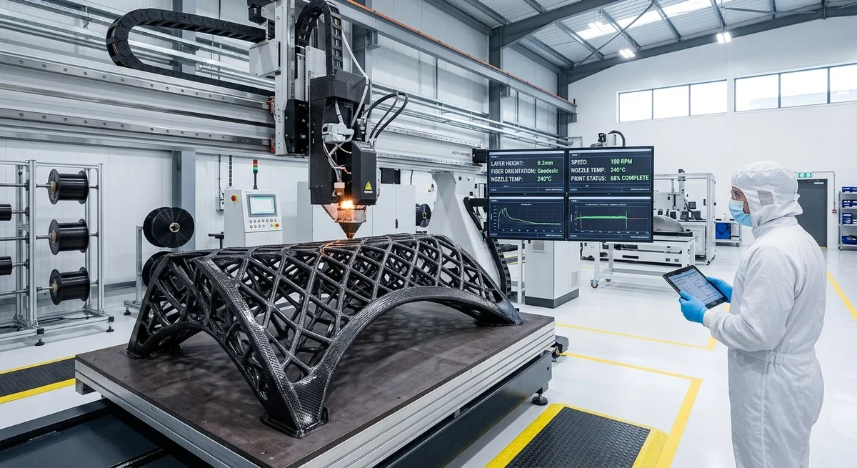
Continuous carbon fiber 3D printing has reached production-ready maturity in 2026. This article reviews key process advances, material systems, and cost benchmarks for industrial adoption.
2026 State of Continuous Carbon Fiber 3D Printing
Continuous carbon fiber reinforced additive manufacturing (CFRAM) has transitioned from lab curiosity to production-capable technology in 2026. Unlike short-fiber filled filaments that offer marginal stiffness gains (10–30% vs neat polymer), continuous fiber deposition achieves fiber volume fractions (FVF) of 45–55%, approaching the mechanical performance of unidirectional prepreg tape — 60–70% of quasi-isotropic laminate properties — without the need for molds, autoclaves, or CNC trimming.
Process Technology Comparison
| Parameter | Markforged X7 (2024) | Desktop Metal Fiber (2025) | 9T Labs Red Series (2026) | Continuous Composites CF3D (2026) |
|---|---|---|---|---|
| Max FVF | 35% | 41% | 55% | 58% |
| Layer thickness (mm) | 0.125 | 0.100 | 0.080 | 0.075 |
| Print speed (mm³/s) | 8 | 15 | 22 | 35 |
| Max build volume (mm) | 330×250×200 | 400×300×300 | 450×350×350 | 1000×600×600 |
| Post-cure required? | No | Yes (120°C) | No (in-situ) | No (UV) |
| Material system | Nylon + CC | PEEK + CC | PEKK + CC | Epoxy + CC |
| Tensile strength (MPa) | 590 | 720 | 950 | 1100 |
| Tensile modulus (GPa) | 50 | 60 | 85 | 110 |
| Machine price (USD) | $69,900 | $89,900 | $149,000 | $250,000 |
| Part cost/kg (USD) | $450 | $380 | $290 | $210 |
Key Technology Advances in 2026
1. In-Situ Consolidation
9T Labs' Red Series and Continuous Composites' CF3D both employ in-situ consolidation — simultaneous fiber deposition and thermoset/thermoplastic curing — eliminating the separate oven-cure step that earlier systems required. This reduces total cycle time by 40–60% and allows closed-loop feedback on interlayer bond strength via inline IR thermography.
2. High-Temperature Thermoplastic Matrices
PEEK (polyether ether ketone) and PEKK (polyether ketone ketone) filaments with continuous carbon fiber towpreg have become standard. These materials offer glass transition temperatures (Tg) above 143°C (PEEK) and 160°C (PEKK), enabling end-use parts in aerospace, oil & gas, and automotive underhood applications. The 2026 price premium over nylon-based systems has narrowed to 15–20% as volume scales.
3. Multi-Axis Deposition
Five-axis and six-axis robotic deposition heads now allow fiber orientation to follow complex curved paths without the stair-stepping artifacts of planar slicing. This reduces the need for support structures by 30–50% and improves interlaminar shear strength (ILSS) by 25–35% compared to 3-axis prints.
Production Readiness Metrics
- Repeatability: Dimensional tolerance ±0.05 mm on parts up to 300 mm (ISO 286 IT8 equivalent)
- Void content: Below 2.5% for thermoset systems, below 3.5% for thermoplastic (ASTM D3171)
- Throughput: 15–35 mm³/s continuous deposition; up to 500 g/hr for complex geometries
- Material utilization: >95% (vs 60–75% for prepreg hand lay-up with trim waste)
- Cost crossover: At batch sizes of 500–5,000 parts per year, CFRAM is cost-competitive with compression molding for non-A-surface components
Cost Analysis for B2B Buyers
| Production Volume (parts/yr) | CFRAM Cost/part | Compression Molding Cost/part | Hand Lay-Up Cost/part |
|---|---|---|---|
| 100 | $420 | $1,850 | $680 |
| 500 | $285 | $520 | $410 |
| 2,000 | $195 | $210 | $290 |
| 10,000 | $155 | $95 | $220 |
Note: CFRAM becomes cost-competitive with compression molding at approximately 2,000–3,000 parts/year for medium-complexity geometries (envelope 200×200×50 mm). Above 10,000 parts, molding tooling amortization favors traditional processes.
Application Segments Adopting CFRAM in 2026
- Aerospace tooling: Drill jigs, assembly fixtures, and lay-up mandrels — 35% weight reduction vs aluminum, 2-week lead time vs 8-week CNC machining
- Industrial robotics: End-effector arms and gripper jaws — stiffness-to-weight ratio 3.2× higher than 6061-T6 aluminum
- Medical prosthetics: Custom-fit carbon fiber sockets and orthoses — patient-specific geometry at no tooling cost
- Oil & gas: Downhole sensor housings and centralizers — corrosion-resistant to H₂S and brine at 150°C
FAQ
Q: How does continuous carbon fiber 3D printing compare to traditional prepreg hand lay-up in terms of mechanical properties?
A: Continuous fiber 3D printing achieves approximately 60–70% of the tensile strength and modulus of a quasi-isotropic hand lay-up laminate at the same FVF. The gap is primarily due to interlayer bond strength (ILSS is 30–40 MPa for CFRAM vs 50–70 MPa for autoclave-cured prepreg). However, for non-primary-structure applications where Z-axis loading is minimal, CFRAM is fully adequate — and the elimination of mold cost, trim waste, and manual labor makes it economically attractive.
Q: What is the current maximum part size for continuous carbon fiber 3D printing in 2026?
A: The largest commercially available system (Continuous Composites CF3D) offers a build volume of 1000×600×600 mm, capable of producing parts up to 1 meter in length. Robotic-arm-based systems with gantry extensions can reach 2×1×1 m, but fiber steering accuracy degrades beyond 0.3° angular deviation at those scales. For parts exceeding 1 meter, segmented print-and-bond strategies are recommended.
Q: Can continuous carbon fiber 3D printing replace metal in structural applications?
A: In bending- and stiffness-dominated designs (beams, brackets, housings), continuous CFRAM parts at 50% FVF achieve specific stiffness (E/ρ) approximately 2.5× that of 6061-T6 aluminum and 4× that of A36 steel. However, for compression-dominated applications (columns, threaded fasteners) and elevated temperatures above 200°C, metal remains superior. The crossover point for weight-neutral replacement of aluminum is at 40% FVF with a structural efficiency factor of 1.8.
Related Articles
- Bio-Based Carbon Fiber Precursors: Lignin and Polyethylene for Low-Cost Production
- Large-Tow Carbon Fiber Cost Analysis: 48K vs 60K Price-Performance Comparison
- Carbon Fiber-Resin Interface Bonding: Surface Treatment and Coupling Agent Optimization
- Digital Twin for Carbon Fiber Manufacturing: Real-Time Process Monitoring and Defect Prevention
- Thermoplastic Carbon Fiber Welding for Automotive: Ultrasonic and Induction Welding Process Windows
- Large-Tow Carbon Fiber Wet Spinning: Process Optimization for 48K/60K Production Efficiency
Interested in Our Products?
Contact our team for competitive pricing and technical specifications.
Get a QuoteRelated Products

Carbon fiber standard plate-3k stripe
Lightweight, ultra-rigid standard sheets for drone fuselages, robot housings, facades and structural applications.

Carbon Fiber Plate — 3K Twill T700 1.5mm
Thin 1.5mm carbon fiber plate with 3K twill weave surface. Lightweight and stiff, commonly used for covers, panels, drone bodies, and applications requiring a premium aesthetic appearance.

Square Carbon Fiber Tube — 3K Twill T700
Square cross-section carbon fiber tube manufactured with 3K twill weave for torsional strength. Preferred for structural frames, trusses, and support columns where rectangular geometry offers design flexibility.

Carbon Fiber Plate — 3K Twill T700 3.0mm
Medium-thickness 3.0mm carbon fiber plate offering significantly higher load capacity while maintaining attractive 3K twill finish. Suitable for structural brackets, reinforcement plates, and load-bearing panels.

Carbon Fiber Plate — UD Unidirectional T700
Unidirectional carbon fiber plate with all fibers oriented in a single direction for maximum strength along the fiber axis. Essential for structural reinforcements, splints, and applications where load direction is predictable.