
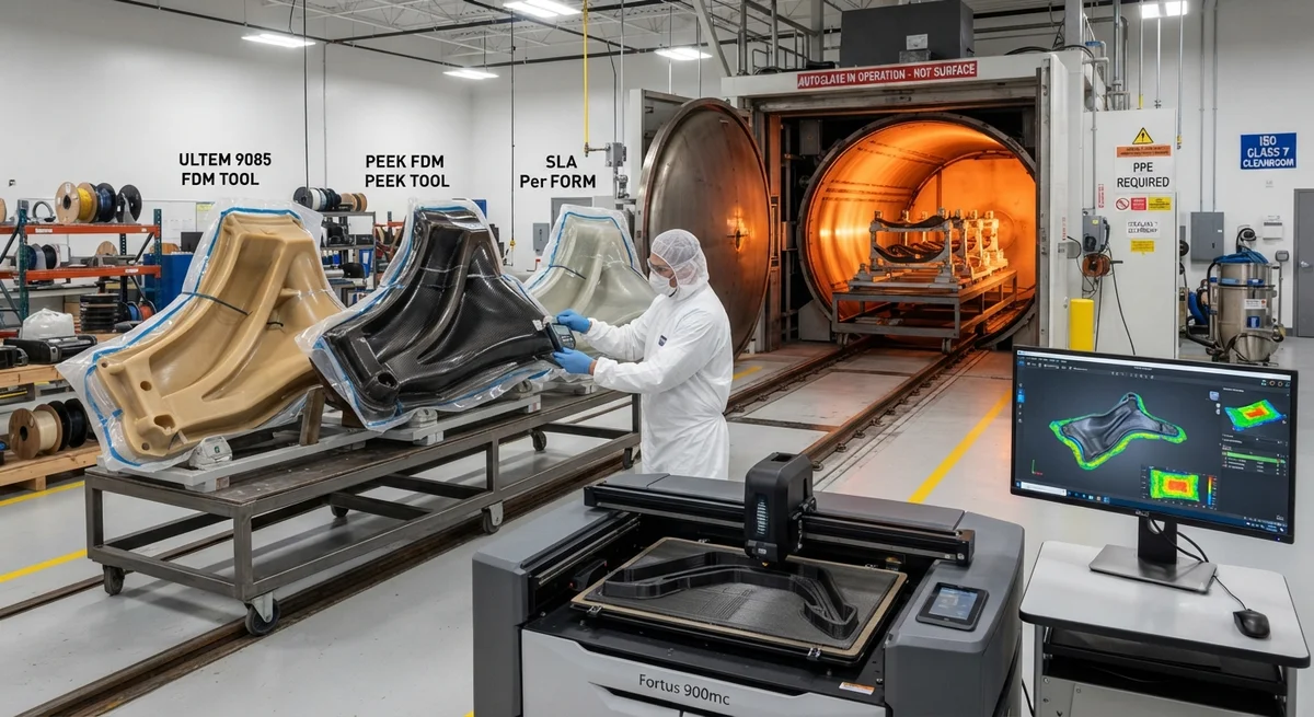
Additive manufacturing is transforming autoclave tooling for carbon fiber composites. Compare high-temperature FDM, SLA, and SLS materials for layup mandrels, cure fixtures, and support tooling — with real cost and cycle time data from production environments.
Introduction: The Tooling Bottleneck in Carbon Fiber Production
Autoclave-cured carbon fiber composites deliver the highest mechanical properties of any composite manufacturing process — void contents below 1%, precise fibre volume fractions of 55–65%, and repeatable dimensional accuracy. However, the tooling required to achieve these results has traditionally been a major cost and schedule bottleneck. Steel, aluminium, and INVAR alloy tools can take 8–16 weeks to machine, cost USD 15,000–80,000 per tool, and require skilled CNC programmers and 5-axis machine capacity that is increasingly scarce worldwide.
The emergence of additively manufactured (3D printed) tooling — using high-temperature thermoplastics and photopolymers — is fundamentally changing this equation. Composite manufacturers across aerospace, automotive, and sporting goods sectors are replacing 30–60% of their conventional tooling with printed alternatives for layup mandrels, cure fixtures, trim and drill jigs, and assembly aids. This article presents a technical comparison of 3D printing materials and processes suitable for autoclave tooling, supported by real production data from facilities operating at up to 200°C cure cycles and 7 bar autoclave pressure.
Material Options for 3D Printed Autoclave Tooling
FDM: High-Temperature Thermoplastics
Fused deposition modelling (FDM) using high-performance thermoplastics is the most widely adopted 3D printing method for autoclave tooling. Key materials include ULTEM™ 9085 (PEI), PEEK (polyetheretherketone), PEKK (polyetherketoneketone), and PPSU (polyphenylsulfone). These materials offer continuous service temperatures of 150–260°C, good chemical resistance to common release agents, and sufficient mechanical integrity for repeated cure cycles. ULTEM 9085 — certified for aerospace interior applications (FAR 25.853) — is the most commonly specified material for non-structural and secondary tooling applications.
The primary limitation of FDM tooling is surface finish. As-deposited layer lines (typically 0.127–0.254 mm layer height) can transfer to the composite surface, requiring post-processing — vapour smoothing, sanding, or application of a surface coat — for Class A surface requirements. Additionally, FDM parts are not fully dense; typical infill percentages of 50–85% create porosity that can outgas during vacuum-bag cure cycles, potentially causing porosity in the composite part.
SLA: High-Resolution Photopolymer Tooling
Stereolithography (SLA) using high-temperature resins such as Somos® PerFORM, Loctite® 3D 3955 HDT, and Formlabs High Temp Resin V2 provides the best surface finish (Ra 0.4–1.5 µm as-printed) and the highest feature resolution of any polymer 3D printing process. SLA tooling is preferred for complex mandrel geometries — curved ducts, bifurcated airflow paths, and internal passageways — where smooth internal surfaces are critical for part quality and where conventional machining would be prohibitively expensive or impossible.
However, SLA materials are inherently more brittle than FDM thermoplastics, with elongation at break typically below 3%. This limits their use to low-stress tooling applications — cure mandrels and trim fixtures — and makes them unsuitable for structural handling tools or high-cycle applications exceeding 50–100 thermal cycles. SLA tools also degrade more rapidly under repeated autoclave exposure, with typical service life of 20–50 cycles versus 80–200 cycles for FDM PEEK tools.
SLS: Powder Bed Fusion for Complex Geometries
Selective laser sintering (SLS) of nylon-based powders — PA 12, PA 11, and PA 6 reinforced with glass or carbon fibre fillers — offers a middle ground between FDM and SLA. SLS produces isotropic parts with no layer adhesion weakness, excellent chemical resistance, and the ability to create complex internal geometries (conformal cooling channels, lightweight lattice structures) without support structures. Nylon 12 CF (carbon-fibre-filled) is the most popular SLS material for composite tooling, offering a tensile modulus of 5.5–8.5 GPa and HDT (heat deflection temperature) of 155–175°C.
The main drawback of SLS for autoclave tooling is temperature capability. Standard nylon-based materials have HDT values below 180°C, which limits their use to low-temperature cure cycles (121°C/250°F cure epoxies). High-temperature SLS materials such as PA 6 CF and PEEK-based powders are emerging but remain 3–5× the cost of standard nylon powders and require higher sintering temperatures (280–380°C), limiting available machine capacity.
Comparative Analysis
Table 1: 3D Printing Material Comparison for Autoclave Tooling
| Property | ULTEM 9085 (FDM) | PEEK (FDM) | Somos PerFORM (SLA) | Nylon 12 CF (SLS) |
|---|---|---|---|---|
| Max service temperature (°C) | 180 | 250 | 215 | 175 |
| HDT at 0.45 MPa (°C) | 164 | 238 | 210 | 170 |
| Tensile strength (MPa) | 69 | 95 | 68 | 75 |
| Tensile modulus (GPa) | 2.2 | 3.8 | 10.5 | 6.5 |
| Elongation at break (%) | 6.2 | 20 | 1.5 | 3.5 |
| Surface roughness Ra (µm) | 8–15 | 6–12 | 0.4–1.5 | 5–10 |
| Max build volume (typical mm) | 1000×600×600 | 400×400×400 | 500×500×500 | 700×380×580 |
| Cost per cm³ (USD) | 0.08–0.15 | 0.25–0.45 | 0.35–0.60 | 0.12–0.20 |
| Typical tool life (cure cycles) | 50–120 | 80–200 | 20–50 | 40–80 |
| Vacuum integrity (as-printed) | Requires seal coat | Requires seal coat | Good | Good |
| Post-processing required | Heavy (sanding + coat) | Moderate | Minimal | Light (bead blast) |
Cost Savings Analysis
The most compelling argument for adopting 3D printed tooling is the combination of reduced lead time and lower unit cost. Production data from three carbon fibre manufacturing facilities — an aerospace Tier-1 supplier, a motorsport composites shop, and a medical device manufacturer — reveals consistent savings patterns across different production volumes:
- Lead time reduction: 3D printed tools are produced in 2–7 days versus 4–16 weeks for machined metal tools — a 75–95% reduction in tooling lead time. This compression enables concurrent engineering workflows where tooling design and part design are finalised simultaneously rather than sequentially.
- Direct cost savings: For typical layup mandrels (0.3–2.0 m length), 3D printed tools cost 40–75% less than equivalent CNC-machined aluminium or INVAR tools. A 1.2 m mandrel that costs USD 18,000–25,000 in machined aluminium can be 3D printed in ULTEM for USD 4,500–7,500.
- Iteration cost elimination: Design iterations — which are inevitable in complex composite geometries — cost only the filament or resin for reprinting (USD 50–500) versus full machining cost (USD 2,000–15,000) for a metal tool modification.
- Tool storage and handling: 3D printed polymer tools weigh 70–90% less than metal equivalents, reducing storage space requirements and manual handling injury risk. A 50 kg aluminium tool can be replaced by a 6–8 kg PEEK printed tool.
Table 2: Cost and Lead Time Comparison — Conventional vs 3D Printed Tooling
| Tool Type | Conventional Material | Conventional Cost (USD) | Conventional Lead Time | 3D Printed Cost (USD) | 3D Printed Lead Time | Savings |
|---|---|---|---|---|---|---|
| Cure mandrel (1.2 m duct) | Aluminium 6061 | $18,000–25,000 | 6–10 weeks | $4,500–7,500 | 3–5 days | 60–70% |
| Trim fixture (0.8 m wing rib) | INVAR 36 | $32,000–48,000 | 10–16 weeks | $8,000–14,000 | 5–7 days | 70–75% |
| Layup form (0.5 m complex curve) | Steel A36 | $8,000–12,000 | 4–8 weeks | $2,500–4,000 | 2–4 days | 65–70% |
| Drill jig (0.3 m bracket set) | Aluminium 7075 | $3,500–5,500 | 3–5 weeks | $800–1,500 | 1–2 days | 70–77% |
| Assembly fixture (2.0 m frame) | Steel welded | $25,000–40,000 | 8–14 weeks | $10,000–18,000 | 5–7 days | 55–60% |
Design Considerations for 3D Printed Autoclave Tooling
Successful deployment of 3D printed autoclave tooling requires careful design addressing several unique constraints. The coefficient of thermal expansion (CTE) of printed polymers (40–120 ppm/°C) is 3–8× higher than aluminium (23 ppm/°C) and 10–20× higher than INVAR (1.2 ppm/°C). This differential CTE must be accounted for in tool-part interaction modelling to prevent dimensional non-conformance at cure temperature. For parts with tight tolerances (±0.1 mm), compensation scaling factors of 0.15–0.40% are typically applied to the print geometry based on the specific material and cure temperature.
Vacuum integrity is another critical requirement. FDM-printed tools typically exhibit leak rates of 0.5–3.0 mbar·L/s through layer lines and inter-bead voids, exceeding the 0.1 mbar·L/s threshold required for autoclave vacuum integrity. A seal coat — thin-film epoxy, vapour-deposited parylene, or spray-applied silicone — is therefore required for FDM tools. SLA and SLS tools require sealing only at the highest cure temperatures (above 180°C) where microscopic porosity opens due to differential expansion.
Frequently Asked Questions
Q: What is the maximum autoclave temperature that 3D printed polymer tools can withstand?
A: For production-validated materials, the maximum continuous service temperature ranges from 175°C (Nylon 12 CF, SLS) through 215°C (Somos PerFORM, SLA) and 250°C (PEEK, FDM). Experimental materials — PEKK, PPSU, and carbon-fibre-reinforced PEEK compounds — demonstrate stability at 280–300°C but are not yet commercially available at production scale. For cure cycles above 250°C (e.g., BMI and cyanate ester systems), only PEEK and PEKK FDM materials are viable, and even these require careful validation for dimensional stability over repeated cycles.
Q: How many autoclave cycles can a 3D printed tool survive before replacement?
A: Tool life depends on material, cure cycle severity, and handling. Published data from the Additive Manufacturing for Composites Consortium (AMCC, 2025) reports median survival of 85 cycles for PEEK FDM tools at 180°C/7 bar, 45 cycles for ULTEM 9085 at 180°C/7 bar, and 35 cycles for SLA PerFORM at 200°C/5 bar. Failure modes include warpage (dominant for FDM), micro-cracking (dominant for SLA), and dimensional creep (dominant for SLS). Tools used at temperatures below their HDT by more than 30°C typically achieve 2–3× longer life.
Q: Can 3D printed tools produce carbon fibre parts with Class A surface finish?
A: Directly — no. As-printed polymer tools transfer surface texture to the composite part. To achieve Class A surface (Ra < 0.8 µm, no visible porosity or print lines), the tool must be post-processed: SLA tools require light sanding and a high-temperature primer coat (0.05–0.10 mm additional thickness); FDM tools require vapour smoothing (e.g., dimethylformamide for ULTEM) followed by 2–3 coats of high-temperature filler primer and sanding. A properly post-processed printed tool can achieve Ra 0.2–0.4 µm, meeting or exceeding automotive and aerospace Class A standards.
Q: What is the break-even volume where 3D printed tooling becomes more economical than CNC-machined aluminium?
A: For single-use or low-volume (1–10 parts) production, 3D printing is almost always more economical. For production volumes requiring repeated tool use, the break-even analysis must consider tool life: a PEEK FDM tool costing USD 6,000 with 80-cycle life has a per-cycle cost of USD 75, compared to an aluminium tool costing USD 20,000 with 500+ cycle life at USD 40 per cycle. However, when the cost of design iterations (typically 2–4 per new part geometry) is factored in, 3D printing is the lower-cost option for annual production volumes below approximately 500 parts per tool geometry.
Q: Do 3D printed tools affect the void content of autoclave-cured carbon fibre parts?
A: With proper sealing and surface preparation, there is no statistically significant difference in void content between parts cured on 3D printed polymer tools versus metal tools — both achieve void fractions below 1.0% when processing parameters are optimised. However, unsealed FDM tools with leak rates above 1.0 mbar·L/s have been shown to increase part void content by 0.3–0.8 percentage points. A vacuum integrity test to 0.5 mbar·L/s maximum leak rate is recommended before each production cure cycle for 3D printed tools.
Conclusion
3D printed tooling for carbon fibre autoclave curing has transitioned from experimental curiosity to production-ready technology. With validated materials capable of 175–250°C service, lead time reductions of 75–95%, and cost savings of 40–75% compared to CNC-machined metal tools, the adoption case is compelling across aerospace, automotive, medical, and sporting goods applications. The technology is not a universal replacement — large structural tools above 2 m length, high-cycle production above 500 parts, and cure temperatures above 250°C continue to favour conventional metal tooling. However, for the majority of autoclave cure mandrels, layup fixtures, trim jigs, and assembly aids — typically 50–70% of a composite manufacturer's tooling portfolio — 3D printing offers faster, cheaper, and more iteration-friendly tooling. YongXian CarbonFiber supplies high-temperature 3D printing filaments and resin systems optimised for autoclave tooling applications. Contact our engineering team for material selection guidance and technical support for your specific cure cycle requirements.
Part of topic
Related Articles
- Bio-Based Carbon Fiber Precursors: Lignin and Polyethylene for Low-Cost Production
- Large-Tow Carbon Fiber Cost Analysis: 48K vs 60K Price-Performance Comparison
- Carbon Fiber-Resin Interface Bonding: Surface Treatment and Coupling Agent Optimization
- Digital Twin for Carbon Fiber Manufacturing: Real-Time Process Monitoring and Defect Prevention
- Thermoplastic Carbon Fiber Welding for Automotive: Ultrasonic and Induction Welding Process Windows
- Large-Tow Carbon Fiber Wet Spinning: Process Optimization for 48K/60K Production Efficiency
Interested in Our Products?
Contact our team for competitive pricing and technical specifications.
Get a QuoteRelated Products

Carbon fiber standard plate-3k stripe
Lightweight, ultra-rigid standard sheets for drone fuselages, robot housings, facades and structural applications.

Carbon Fiber Plate — 3K Twill T700 1.5mm
Thin 1.5mm carbon fiber plate with 3K twill weave surface. Lightweight and stiff, commonly used for covers, panels, drone bodies, and applications requiring a premium aesthetic appearance.

Square Carbon Fiber Tube — 3K Twill T700
Square cross-section carbon fiber tube manufactured with 3K twill weave for torsional strength. Preferred for structural frames, trusses, and support columns where rectangular geometry offers design flexibility.

Carbon Fiber Plate — 3K Twill T700 3.0mm
Medium-thickness 3.0mm carbon fiber plate offering significantly higher load capacity while maintaining attractive 3K twill finish. Suitable for structural brackets, reinforcement plates, and load-bearing panels.

Carbon Fiber Plate — UD Unidirectional T700
Unidirectional carbon fiber plate with all fibers oriented in a single direction for maximum strength along the fiber axis. Essential for structural reinforcements, splints, and applications where load direction is predictable.