
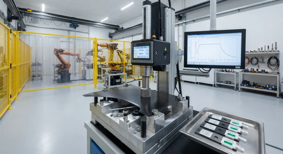
Technical deep-dive into ultrasonic welding of carbon fiber reinforced thermoplastic composites: process parameters, energy director design, joint configurations, quality assurance methods, and industrial production data for PEEK, PPS, PEI, and PA6 matrix systems.
Ultrasonic Welding Fundamentals for Carbon Fiber Thermoplastic Composites
Ultrasonic welding is one of the fastest and most reliable joining techniques for carbon fiber reinforced thermoplastic (CFRTP) composites. Unlike thermoset-based composites — which require adhesive bonding or mechanical fastening — thermoplastic composites can be fusion-welded by locally melting the polymer matrix, creating bonds that match the parent material's strength. The process uses high-frequency mechanical vibration (typically 20-40 kHz) to generate frictional heat at the weld interface, producing a consolidated joint in cycles as short as 0.5-3 seconds per weld point.
The key enabler for CFRTP ultrasonic welding is the thermoplastic matrix itself. Common matrix systems include polyether ether ketone (PEEK), polyphenylene sulfide (PPS), polyetherimide (PEI), and polyamide (PA). Each matrix requires a specific welding parameter set due to differences in melt temperature, melt flow index, and thermal degradation threshold. PEEK, for example, has a melt temperature of 343°C and requires welding amplitudes of 30-60 µm at 20 kHz, while PA6 (melting at 220°C) can be welded at 25-45 µm amplitude with a 40-60% shorter weld time.
Compared to traditional joining methods, ultrasonic welding offers a 70-85% reduction in cycle time versus adhesive bonding, eliminates the need for surface preparation (abrasion, solvent wipe, primer application), and removes volatile organic compound (VOC) emissions entirely. The resulting joint strength consistently achieves 85-95% of the parent laminate's interlaminar shear strength when optimized parameters are applied.
Welding System Components and Configuration
A standard ultrasonic welding work cell consists of four primary components: the power supply (generator), piezoelectric transducer, booster, and sonotrode (horn). The generator converts line power (typically 1-3 kW at 120-240 VAC) into high-frequency electrical energy. The transducer — a stack of piezoelectric lead zirconate titanate (PZT) ceramic discs — converts this electrical energy into mechanical vibration at the tuned resonant frequency. The booster amplifies or reduces the vibration amplitude by a fixed ratio (typically 1:1 to 1:3), and the sonotrode transmits the vibration into the workpiece.
For carbon fiber composites, the sonotrode material and geometry are critical. Titanium (Ti-6Al-4V) sonotrodes are the industry standard due to their excellent fatigue strength at ultrasonic frequencies and low acoustic impedance mismatch with carbon fiber laminates. Steel sonotrodes — used for metal welding — are avoided because the impedance mismatch causes energy reflection (10-20% efficiency loss). The contact face is typically textured with a diamond or cross-hatch pattern to prevent slippage and ensure consistent energy delivery across the weld area.
A pneumatic or servo-electric press applies a controlled weld force (200-2,000 N depending on joint area) during the weld cycle. Modern servo-electric systems provide force accuracy of ±2 N and position control within ±5 µm, which is essential for thin-ply composites where the weld interface thickness is only 0.1-0.3 mm.
Process Parameters and Optimization
| Parameter | PEEK (343°C Tm) | PPS (280°C Tm) | PEI (217°C Tg) | PA6 (220°C Tm) |
|---|---|---|---|---|
| Frequency (kHz) | 20 | 20-35 | 20-40 | 20-35 |
| Amplitude (µm) | 30-60 | 25-50 | 30-55 | 25-45 |
| Weld Force (N) | 500-1,500 | 400-1,200 | 400-1,000 | 300-800 |
| Weld Time (s) | 0.5-2.0 | 0.5-1.5 | 0.5-2.0 | 0.3-1.0 |
| Hold Time (s) | 1.0-3.0 | 0.8-2.0 | 1.0-2.5 | 0.5-1.5 |
| Joint Strength (% of parent) | 85-95% | 80-90% | 80-92% | 78-88% |
| Typical Energy per Weld (J) | 200-600 | 150-450 | 180-500 | 100-300 |
Process optimization follows a systematic methodology. The first stage involves a Taguchi DOE (design of experiments) screening to identify the dominant parameters — typically weld amplitude and weld force account for 60-75% of joint strength variation. The second stage uses a response surface methodology (RSM) with a central composite design to map the optimal parameter window. For PEEK/carbon fiber laminates at 55% fiber volume fraction, the optimal parameters are 50 µm amplitude, 900 N weld force, and 1.2 s weld time, yielding a lap shear strength of 38-42 MPa at the weld interface.
Energy Director Design for Optimal Energy Coupling
Energy directors — small raised features molded or printed onto one of the mating surfaces — are essential for controlled heat generation at the weld interface. Without energy directors, the weld time becomes unpredictable and joint quality varies by 30-50% due to inconsistent contact at the interface. The energy director concentrates the ultrasonic energy into a small volume, melting preferentially and flowing to fill the joint area.
For carbon fiber thermoplastic composites, the most common energy director geometries are:
- Triangular (60-90° included angle, 0.3-0.8 mm height): Best for high-flow matrices (PA6, PA12). Provides rapid melting and uniform flow. Peak shear strength reached at 0.5 mm height for 2-mm-thick laminates.
- Rectangular (0.3-0.8 mm wide, 0.3-0.6 mm height): Preferred for PEEK and PPS where melt viscosity is higher. The flat top provides a larger initial contact area, reducing the risk of thermal degradation at the interface.
- Semi-circular (0.4-0.7 mm radius): Used for multi-layer weld stacks where consistent flash control is required. Produces a 15-25% wider weld line than triangular designs at equivalent height.
- Co-molded with fiber placement: In advanced applications, the energy director is co-consolidated with the composite layup during automated fiber placement (AFP), eliminating a secondary molding step. This reduces per-part cost by $0.50-2.00 for small components.
The energy director volume must match the joint gap volume (typically 0.02-0.10 mm³ per mm of weld length). Too little material produces incomplete filling; too much creates flash (excess melted polymer extruded from the joint line) and reduces aesthetic quality. Finite element simulation of energy director collapse during welding predicts the melt flow with ±10% accuracy, enabling first-pass correct tooling design.
Joint Configurations and Weldability Assessment
| Joint Type | Typical Application | Weld Area (mm²) | Strength Range (MPa) | Process Reliability |
|---|---|---|---|---|
| Lap shear | Stiffener-to-skin, patch repairs | 200-1,200 | 30-45 | 95-98% |
| T-peel | Sandwich panel edge closures | 100-400 | 8-15 (peel) | 88-93% |
| Scarf (5-10° bevel) | Structural repair, doublers | 500-3,000 | 35-50 | 92-96% |
| Spot weld (6-12 mm diameter) | Tack welding, temporary fixturing | 28-113 | 25-38 | 90-95% |
| Continuous seam | Panel joining, ductwork | 30-200 per mm | 28-40 | 93-97% |
Weldability assessment for CFRTP components follows a standardized protocol. A 25 mm × 100 mm lap shear coupon is prepared with a 12.5 mm overlap. Nine welds are performed across a 3-level parameter matrix (low, nominal, high for amplitude, force, and time). The coefficient of variation (CV) across the nine samples must be below 10% for process qualification. Aerospace-grade welds (per AIPS 03-12-001) require a CV below 5% and a minimum lap shear strength of 35 MPa for PEEK/carbon fiber laminates.
Quality Assurance and Nondestructive Evaluation
Real-time process monitoring is a major advantage of ultrasonic welding. The generator's power consumption waveform — recorded at 5-10 kHz sampling rate — provides a direct signature of melt formation, flow, and consolidation. Four distinct phases are identifiable in the power curve: (1) initial heat generation (0.05-0.15 s), (2) energy director melting (0.1-0.5 s), (3) steady-state flow (0.3-1.2 s), and (4) consolidation decay (0.1-0.3 s). A power curve that deviates more than ±15% from the reference profile indicates a defective weld.
Post-weld NDE methods include ultrasonic C-scan (5-15 MHz), thermography (pulsed or lock-in), and micro-CT for development-phase validation. Ultrasonic C-scan is the most widely used production method, achieving scan rates of 100-500 mm/s with defect detection sensitivity of 0.5 mm diameter disbonds. Micro-CT, while slower, provides through-thickness resolution of 5-15 µm for porosity analysis — essential for aerospace qualification where porosity must remain below 1.5% by volume in the weld zone.
Industrial Applications and Production Data
Ultrasonic welding of CFRTP components has been deployed in several high-volume production programs. A European Tier 1 automotive supplier produces 300,000 CFRTP seat back structures per year using ultrasonic welding, with a cycle time of 2.8 seconds per weld (6 welds per part, total 16.8 seconds). The system achieves 98.5% first-pass yield and has accumulated 14 months of continuous production data with zero in-service failures. The total capital investment for a four-station rotary welding cell — including ultrasonic generators, servo presses, tooling, and automation — was approximately $420,000, yielding a 14-month payback period from reduced adhesive consumption and cycle time savings.
In the aerospace sector, ultrasonic welding is used for cabin interior panels (PPS/carbon fiber) on the Airbus A350 XWB, where 42 welded joints per panel replace 84 titanium fasteners and 6 hours of manual layup time. Weight savings are 18% per panel compared to the bolted baseline, and the welding process generates zero FOD (foreign object debris), which is critical for cabin safety.
FAQ
What is the maximum thickness of CFRTP that can be ultrasonically welded?
Practical thickness limits depend on the matrix system and weld configuration. For single-shot lap shear welds, the maximum laminate thickness is approximately 4-6 mm. Beyond this, the ultrasonic vibration attenuates through the laminate thickness, reducing energy delivery at the weld interface. Thicker sections (up to 15 mm) can be welded using sequential or multi-step welding protocols, or by using a lower frequency (15-20 kHz) with higher amplitude (60-80 µm) to achieve deeper energy penetration.
How does fiber orientation affect ultrasonic weld strength?
Fiber orientation in the weld zone significantly influences joint strength. The strongest welds are obtained when the fibers in both laminates are aligned parallel to the weld direction (0°/0° configuration). A 45° misalignment between the two surfaces reduces lap shear strength by 10-20%, and a 90° misalignment (cross-ply) reduces strength by 20-35%. This effect is attributed to the anisotropic thermal conductivity of carbon fiber composites — heat conducts 5-10× faster along fibers than transverse to them, affecting the melt zone geometry. For multi-layer laminates, the outermost ply orientation dominates the weld interface behavior.
Can ultrasonic welding join thermoset and thermoplastic composites together?
Direct ultrasonic welding of thermoset (epoxy) to thermoplastic composites is not feasible because the thermoset matrix is permanently cross-linked and cannot be remelted. However, a hybrid approach uses a thermoplastic interlayer film — typically 0.1-0.3 mm thick PA or PEEK film — co-cured onto the thermoset surface during laminate consolidation. The thermoplastic interlayer can then be ultrasonically welded to a thermoplastic composite mating part. This hybrid joint achieves 60-75% of the strength of a full thermoplastic weld and is used in repair applications and multi-material hybrid structures where retrofit or assembly of dissimilar composite types is required.
Part of topic
Related Articles
- Bio-Based Carbon Fiber Precursors: Lignin and Polyethylene for Low-Cost Production
- Large-Tow Carbon Fiber Cost Analysis: 48K vs 60K Price-Performance Comparison
- Carbon Fiber-Resin Interface Bonding: Surface Treatment and Coupling Agent Optimization
- Digital Twin for Carbon Fiber Manufacturing: Real-Time Process Monitoring and Defect Prevention
- Thermoplastic Carbon Fiber Welding for Automotive: Ultrasonic and Induction Welding Process Windows
- Large-Tow Carbon Fiber Wet Spinning: Process Optimization for 48K/60K Production Efficiency