
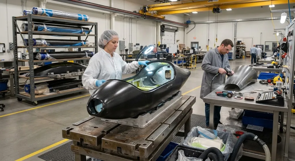
For a reconnaissance UAV, the fuselage is not just a box that holds components — it is the structural backbone that carries payload, fuel, and avionics through the most demanding flight envelope the aircraft will ever see, and it is the aerodynamic surface that determines how efficientl
Introduction
For a reconnaissance UAV, the fuselage is not just a box that holds components — it is the structural backbone that carries payload, fuel, and avionics through the most demanding flight envelope the aircraft will ever see, and it is the aerodynamic surface that determines how efficiently the aircraft converts its limited energy into range and endurance. Carbon fiber composites dominate this application because no other material system combines the three properties that matter most: a stiffness-to-weight ratio roughly four times that of aluminum, the ability to be molded into complex aerodynamic shapes, and electromagnetic transparency where the design needs radar, antenna, and sensor apertures.
This article is written for UAV manufacturers, integrators, and defense program buyers who need to understand how carbon fiber monocoque fuselages are designed and built. We cover the monocoque design philosophy and how it differs from truss and semi-monocoque structures, the two dominant manufacturing routes — autoclave prepreg and resin transfer molding — and the sensor integration challenges that turn a good aerodynamic shell into a working reconnaissance platform.
Monocoque vs Truss and Semi-Monocoque Structures
The structural philosophy of a fuselage decides its weight, its manufacturing cost, and its survivability. Three approaches cover the design space, and each has a place:
- Truss structures: A framework of tubes or struts carries the loads, with a thin skin providing aerodynamic shape but little structural function. Trusses are simple and cheap but heavy, and the skin adds weight without earning its keep structurally.
- Semi-monocoque: A stressed skin works together with longitudinal stringers and transverse frames, as in most commercial aircraft. Semi-monocoque is robust and inspectable but relies on many mechanical joints, which add weight and assembly cost.
- Monocoque: A single continuous shell — the skin itself — carries essentially all the structural loads. There are no frames or stringers; stiffness comes from the shell's geometry, curvature, and skin thickness distribution. This is where carbon fiber shines, because the material's directional strength can be aligned with the load paths that a monocoque shell must carry.
For UAVs, the monocoque approach wins on weight because every gram of fuselage structure is a gram of lost payload or endurance. A carbon fiber monocoque fuselage is typically 20-35% lighter than an equivalent semi-monocoque metal structure at the same stiffness, because it eliminates the redundant stringers and frames that metal designs need to stabilize thin skins. The trade-off is that a monocoque shell is harder to repair — damage tends to propagate along the skin rather than stop at a frame — which is why damage-tolerant design and defined inspection points are built into the fuselage from the start.
Manufacturing Routes: Autoclave Prepreg and RTM
Two manufacturing routes dominate carbon fiber fuselage production, and the choice between them drives cost, cycle time, and achievable skin quality.
| Process | Autoclave Prepreg | Resin Transfer Molding (RTM) |
|---|---|---|
| Material input | Pre-impregnated unidirectional tape and fabric | Dry fiber preform + injected resin |
| Fiber volume fraction | 55-65% | 50-60% |
| Skin quality | Excellent, low void content | Good, depends on injection control |
| Cycle time | Hours per part, autoclave batch | Shorter, resin cures in mold |
| Tooling cost | Moderate, single-sided + vacuum bag | Higher, matched closed molds |
| Typical use | Prototypes, low-rate production, high-performance skins | Mid-rate production, complex geometries |
Autoclave prepreg is the workhorse for high-performance reconnaissance fuselages. Prepreg offers precise control of fiber orientation and fiber volume fraction, and the autoclave's combined pressure and temperature produce skins with void content below 1-2%, which matters for fatigue life and consistent mechanical properties. The process is labor-intensive and batch-based, which limits throughput, but for fuselage programs measured in hundreds of units rather than thousands, it remains the most reliable route to a certified-quality skin.
Resin transfer molding injects liquid resin into a closed mold containing a dry fiber preform. RTM can produce more complex geometries in shorter cycles and can integrate inserts, stiffeners, and sensor housings directly into the molded part, reducing assembly work. The trade-off is tooling cost — matched closed molds are expensive — and slightly lower fiber volume fraction. Many modern UAV programs use RTM for the high-volume structural components and prepreg for the skin panels and bonded assemblies, combining the strengths of both routes.
Material Selection for UAV Fuselages
Fuselage material selection is a balancing act between stiffness, weight, cost, and manufacturability. The practical choices break down as follows:
- Intermediate-modulus carbon fiber: The default for structural fuselage skins, offering the best balance of stiffness, strength, and cost for most UAV programs.
- High-modulus fiber: Used selectively where maximum stiffness per gram is required, such as wing spars and long slender fuselage sections, at higher cost and lower strain-to-failure.
- Fabric vs unidirectional: Woven fabric handles curvature and complex mold shapes more easily and provides better impact resistance; unidirectional tape provides maximum stiffness in the load direction. Most fuselages use a hybrid of both.
- Core materials: Foam or honeycomb cores in sandwich panels stiffen large flat skin areas against buckling and panel flutter without adding significant weight, at the cost of added manufacturing steps.
The stiffness requirement deserves particular attention for reconnaissance platforms because of payload. A gimballed EO/IR sensor, a synthetic aperture radar, or a signals intelligence payload can weigh tens of kilograms and must be pointed with precision during flight. The fuselage skin and the payload bay structure must hold that mass rigidly enough that vibration and flexure do not blur the imagery or degrade the radar beam.
Sensor Integration and Apertures
A reconnaissance fuselage is defined by its payload apertures as much as by its structure. The sensor integration decisions made during design determine whether the aircraft can actually do its mission:
- Radome and antenna windows: Carbon fiber is electrically conductive, so it blocks electromagnetic signals. Where the design needs a radar antenna or communication link, the skin must be replaced with a radome material — typically fiberglass or quartz fiber laminate, or a carbon-free region with a dielectric skin — and the transition zone between the conductive and non-conductive regions must be engineered to avoid signal reflection.
- Gimbal and payload mounting: The payload bay must be stiff enough to hold a gimballed sensor without resonance at flight vibration frequencies, and the mounting hardpoints must be integrated into the fuselage structure during molding rather than added afterward.
- Venting and environmental control: Sensor apertures need controlled pressure and temperature environments, which means sealed bays, vents, and structural provisions for cooling ducts and avionics heat management.
- Structural integrity of apertures: Every cutout — sensor window, camera aperture, cooling vent — is a stress concentration in the monocoque shell, so cutout edges are reinforced with local buildups or doublers, and the design must keep the reinforced cutouts within the fatigue and damage-tolerance envelope.
| Integration Element | Design Consideration | Typical Solution |
|---|---|---|
| Radar/antenna aperture | Carbon blocks RF signals | Dielectric radome, quartz or glass fiber skin |
| EO/IR gimbal mount | Vibration-free pointing | Stiff payload bay, integrated hardpoints |
| Cutouts and vents | Stress concentration, environmental seal | Local reinforcement, sealed bays, doublers |
| Battery/fuel bay | Weight distribution, access | Removable access panels, bonded-in rails |
Getting the electromagnetic design right is often the difference between a fuselage that flies and a fuselage that performs its mission. A carbon monocoque that looks perfect aerodynamically but blocks the radar or the datalink is a demonstration aircraft, not a reconnaissance asset.
Qualification and Testing
Before a monocoque fuselage enters service, it must survive a defined structural test program. The typical sequence mirrors manned aircraft practice, scaled to the UAV's loads:
- Coupon and element testing: Material allowables for the laminate system, generated per ASTM standards, provide the design basis.
- Static test: A full fuselage is loaded to limit and ultimate load factors — typically 3.8g to 5.5g for tactical UAVs, depending on the mission — while strain gauges verify the analytical predictions.
- Fatigue and damage tolerance: Repeated load cycles representative of the service spectrum, plus demonstrated behavior with representative impact damage, verify that the fuselage survives its design life and retains strength with damage present.
- Ground and flight test: Vibration, environmental, and flight test campaigns validate the structural, aerodynamic, and sensor integration assumptions together.
The test program is where manufacturing quality shows. Voids, ply wrinkles, and poor bond lines that look acceptable on the shop floor reveal themselves under load, which is why ultrasonic inspection of skins and bond lines is a mandatory step in fuselage production. A monocoque shell has no redundant structure to catch a defect — the quality of the laminate is the quality of the aircraft.
Frequently Asked Questions
Why is a carbon fiber monocoque better than an aluminum frame for a UAV fuselage?
Weight and stiffness are the two decisive reasons. Carbon fiber has a stiffness-to-weight ratio roughly four times that of aluminum, so a monocoque shell delivers the same fuselage stiffness at 20-35% lower weight than an equivalent metal semi-monocoque structure. For a reconnaissance UAV, that weight saving converts directly into payload, fuel, or battery — which means longer endurance and range. Carbon fiber also allows complex aerodynamic shapes that would be expensive or impossible in metal, and the directional properties of the laminate can be aligned with the actual load paths. The trade-offs are higher material cost, longer manufacturing cycles, and repair complexity, which is why the engineering must account for damage tolerance and defined inspection from the start.
Can a carbon fiber fuselage be repaired in the field?
Yes, within defined limits. Minor damage — small delaminations, surface gouges, and edge chips within the documented limits — can be repaired with bonded patch procedures using the same prepreg or wet-layup materials, restoring both structure and the original load capability. Field repair kits are available for tactical UAVs, and the repair procedures are defined in the aircraft maintenance manual. Larger structural damage, such as a through-crack or a large impact area, typically requires returning the fuselage to a certified repair facility or replacing the affected skin section, because a monocoque shell carries all its loads through the skin and an improperly repaired section becomes the weak link. The inspection and repair philosophy should be agreed with the manufacturer before the fleet enters service.
How does a carbon fiber fuselage handle electromagnetic signals for sensors and antennas?
Carbon fiber is an electrical conductor, so a continuous carbon skin blocks or reflects electromagnetic signals rather than passing them. For radar antennas, communication links, and GPS receivers, the skin must include a radome region made of a dielectric material — typically glass or quartz fiber laminate, or a sandwich with a non-conductive core — that lets the signals pass while carrying the structural loads. The transition between the conductive carbon region and the dielectric region is a design detail: it must avoid creating a reflecting edge and must handle the strain compatibility between the two materials. Modern reconnaissance fuselages design these apertures into the laminate and tooling from the start, because adding them to a finished carbon shell is structurally and electromagnetically very difficult.
What determines the endurance of a reconnaissance UAV?
Endurance is governed by the balance between available energy — fuel or battery — and the power required to fly, and the fuselage influences both sides. Fuselage weight subtracts directly from the energy-carrying payload margin: every kilogram saved in structure can be carried as fuel or battery instead. Fuselage aerodynamics determine the drag the propulsion system must overcome, and a clean monocoque shape with integrated sensor housings keeps drag low. The structural stiffness also matters indirectly, because a flexible fuselage can develop vibration or control-coupling issues that force the flight controller to fly conservatively, burning more energy. A well-designed carbon monocoque contributes on all three fronts, which is why it is the standard choice for endurance-critical reconnaissance platforms.
Conclusion
Carbon fiber monocoque construction gives reconnaissance UAVs the weight advantage, stiffness, and aerodynamic freedom that endurance missions demand. The monocoque philosophy eliminates redundant structure, the prepreg and RTM manufacturing routes offer different balances of quality and throughput, and sensor integration — from radomes to gimbal hardpoints to cutout reinforcement — is engineered into the laminate rather than added afterward. The result is a fuselage that converts its weight budget into mission capability instead of structure.
For UAV manufacturers and defense program buyers, the path to a successful fuselage runs through material selection, process choice, and qualification discipline. Explore our carbon fiber prepreg, fabric, and unidirectional sheet range for UAV structural applications, or contact our engineering team to discuss material specifications and manufacturing support for your aircraft program.
Part of topic
Related Articles
- Carbon Fiber Tubes for Sale: Spec Sheet Fields That Actually Matter
- Carbon Fiber Sheets Near Me: Local Dealers and Quick Turnaround Procurement
- Carbon Fiber Tubes Near Me: Local Stock Availability and Same-Day Delivery Options
- Carbon Fiber Plate Orthotic: Lightweight Prosthetic and Medical Device Applications
- Carbon Fiber Sheets 6mm: Specifications, Load Ratings and Application Guide
- Carbon Fiber Rod Grips: Ergonomic Handle Design for Industrial and Sport Applications
Interested in Our Products?
Contact our team for competitive pricing and technical specifications.
Get a QuoteRelated Products

Carbon Fiber Plate — 3K Twill T700 1.5mm
Thin 1.5mm carbon fiber plate with 3K twill weave surface. Lightweight and stiff, commonly used for covers, panels, drone bodies, and applications requiring a premium aesthetic appearance.

Carbon Fiber Plate — 3K Twill T700 3.0mm
Medium-thickness 3.0mm carbon fiber plate offering significantly higher load capacity while maintaining attractive 3K twill finish. Suitable for structural brackets, reinforcement plates, and load-bearing panels.

Square Carbon Fiber Tube — 3K Twill T700
Square cross-section carbon fiber tube manufactured with 3K twill weave for torsional strength. Preferred for structural frames, trusses, and support columns where rectangular geometry offers design flexibility.

Carbon Fiber Plate — UD Unidirectional T700
Unidirectional carbon fiber plate with all fibers oriented in a single direction for maximum strength along the fiber axis. Essential for structural reinforcements, splints, and applications where load direction is predictable.

Round Carbon Fiber Tube — UD Unidirectional T700
Unidirectional (UD) round tube with all fibers aligned axially for maximum longitudinal stiffness. Ideal for applications requiring high bending rigidity with minimal weight, such as shafts, struts, and structural reinforcements.