
In geostationary orbit, a satellite reflector alternates between direct sunlight and the cold shadow of Earth roughly every 90 minutes, cycling through temperature differences of 200 C or more. Despite this, the reflector surface must stay within a fraction of a millimeter of its design
Introduction
In geostationary orbit, a satellite reflector alternates between direct sunlight and the cold shadow of Earth roughly every 90 minutes, cycling through temperature differences of 200 C or more. Despite this, the reflector surface must stay within a fraction of a millimeter of its design shape, because surface error directly degrades antenna gain: a distorted reflector turns a focused beam into a blurred one. This is the fundamental challenge of satellite reflector design, and it is why carbon fiber composites dominate the application.
The carbon fiber solution works through two material properties. First, the coefficient of thermal expansion (CTE) of a carbon fiber laminate can be engineered to near zero by balancing fiber orientation — the negative CTE of the fiber along its axis offsets the positive CTE of the resin matrix. Second, carbon fiber's high specific stiffness lets a honeycomb sandwich reflector be built light enough to fly while rigid enough to hold its shape. This article explains how CFRP reflectors achieve precision geometry, how they are manufactured, and what data define their performance.
The Precision Requirement
Antenna performance scales with surface accuracy through a simple rule: acceptable surface error is roughly one-twentieth of the operating wavelength. A Ku-band reflector operating at 12-14 GHz has a wavelength near 22 mm, allowing a surface RMS error of roughly 1.0-1.2 mm. A Ka-band reflector at 30 GHz tightens the allowance to about 0.4-0.5 mm RMS. High-end missions — including many Earth observation and deep-space communication antennas — specify 0.1-0.3 mm RMS, which leaves almost no room for thermal, gravity, or manufacturing error.
Two dominant error sources must be controlled simultaneously. Thermal deformation from the orbital temperature cycle is the largest and is addressed by CTE engineering. Manufacturing error, including tooling precision and cure distortion, sets the initial shape from which all other errors start.
Near-Zero CTE Laminate Design
The thermal behavior of a CFRP laminate comes from the opposing thermal responses of its constituents. Carbon fiber shrinks slightly as temperature rises (negative CTE along the fiber axis, typically -0.5 to -1.0 ppm/K), while epoxy resin expands (50-70 ppm/K). In a laminate, the net in-plane CTE is a weighted average governed by fiber volume fraction and the stiffness contribution of each ply orientation. By selecting ply angles and stacking sequence, designers tune the laminate CTE across a range from about -1 to +2 ppm/K — down to near zero.
Three refinements improve stability further. Pseudo-isotropic or quasi-isotropic stacking sequences balance in-plane CTE in all directions, preventing asymmetric distortion. High-modulus carbon fibers, with their larger negative CTE and higher stiffness, allow near-zero CTE with lower fiber volume fractions, which is why high-modulus grades are standard in reflector face skins.
The same design logic extends to the honeycomb core. Aluminum honeycomb is the common choice for its strength and availability, but its CTE of 23 ppm/K must be decoupled from the carbon skins — which the sandwich geometry does naturally, since the core carries shear while the skins carry in-plane load.
Sandwich Construction and Structural Details
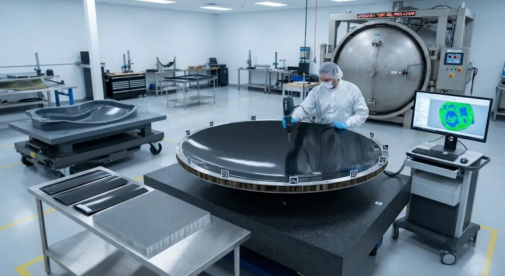
A typical solid reflector is a sandwich structure: two thin CFRP face skins bonded to a honeycomb core, with an edge ring or rib structure to carry the mounting interface. The skins are 0.3-1.0 mm thick laminates of high-modulus fiber; the core is 10-50 mm of honeycomb depending on reflector size and stiffness needs; the whole assembly is cured in an autoclave. The sandwich achieves exceptional stiffness-to-weight: a 1.5 m diameter reflector with 30 mm core and 0.5 mm skins weighs roughly 8-12 kg yet holds its surface profile within the specified RMS under thermal and dynamic loads.
- Skin layup: High-modulus carbon fiber in epoxy, quasi-isotropic layup, typically 4-12 plies depending on stiffness requirements and reflector diameter.
- Core selection: Aluminum honeycomb for standard reflectors; carbon or aramid honeycomb for the most thermally demanding missions.
- Edge treatment: The reflector rim is reinforced with a CFRP edge band or machined aluminum ring that carries the mounting lugs and absorbs handling loads.
- Fitting interfaces: Invar or titanium fittings match the reflector CTE where metallic interfaces are unavoidable, avoiding local distortion around mount points.
- Surface finishing: A conductive coating is applied to the reflector surface to satisfy RF grounding and static discharge requirements, without disturbing the mechanical profile.
The mounting interface is where stability is most easily lost. A metallic mount with a mismatched CTE will locally distort the reflector as temperature changes, which is why reflector manufacturers use Invar (CTE 1-2 ppm/K, close to the CFRP laminate) or composite fittings at load introduction points. For deployable reflectors — which fold for launch and open in orbit — the hinges and latches use the same CTE-matched design logic to return the surface to its precise shape after deployment.
Manufacturing: Tooling and Cure Control
Reflector precision is made or lost at the tooling stage. The reflector is cured on a precision mold — typically machined Invar or a graphite-epoxy tool — whose surface is the negative of the required reflector shape. Invar tooling is standard because its near-zero CTE matches the laminate during the cure temperature cycle, keeping the part within tolerance as both heat and cool together. High-precision molds are machined on five-axis CNC equipment and verified by laser interferometry or photogrammetry to the required surface tolerance.
Cure distortion is the second manufacturing challenge. As the laminate cures and cools, the differential CTE between the part and the tool, plus resin shrinkage and fiber spring-in at curved edges, can distort the surface. Designers compensate with tool surface offsets determined from a combination of finite element prediction and trial parts. After cure, the reflector surface is measured and the measurement feeds back into the tool offset for the next iteration until the process converges on the required RMS.
For very large reflectors, segmentation becomes necessary. Reflectors beyond about 4-6 m in diameter are built as segments or panels that are assembled and aligned on an optical bench, with the final surface verified by coordinate measuring machines or photogrammetry across the full aperture. Deployable reflectors for synthetic aperture radar and communication missions take this further: panels are folded around a mechanism and must re-open to the same precise surface, which requires the same CTE-matched materials in the deployment structure as in the reflector itself.
Performance Data and Comparison
| Parameter | CFRP Sandwich Reflector | Aluminum Reflector | Note |
|---|---|---|---|
| In-plane CTE (ppm/K) | -0.5 to +1.0 (tunable) | ~23 | CFRP can be tuned near zero |
| Specific stiffness (GPa/(g/cm³)) | 85-140 (high-modulus skins) | 26 | 3-5 times stiffer per unit mass |
| Surface RMS achievable (mm) | 0.1-0.3 (precision) | 0.3-1.0 | Driven by tooling and CTE |
| Thermal distortion at 200 C swing | Near-zero (CTE-tuned) | Several mm | CFRP holds shape through orbit |
| Typical areal mass (kg/m²) | 4-7 | 8-15 | Sandwich efficiency |
| Structural efficiency (mass per aperture area) | Best | Moderate | CFRP favored for large apertures |
| Cost index per reflector | 1.0 (baseline) | 0.4-0.7 | CFRP higher, justified by stability |
The data show why aluminum — the default structural material of the space industry — is displaced by carbon fiber for reflectors wherever precision matters. An aluminum reflector of the same size distorts by millimeters across the orbital temperature cycle, an order of magnitude beyond the acceptable error at Ku-band frequencies. The CFRP reflector trades higher material and tooling cost for a shape that does not move.
Frequently Asked Questions
Why can't aluminum reflectors meet precision requirements on modern satellites?
Aluminum's coefficient of thermal expansion is about 23 ppm/K, so a 1.5 m reflector would expand or contract by more than 3 mm across a 200 C orbital temperature swing — an order of magnitude beyond the 0.1-0.5 mm RMS error allowed at Ku and Ka band. Designers can mitigate this with stiffening ribs and thermal control blankets, but these add mass and complexity. A CFRP laminate tuned to near-zero CTE holds the same reflector within a few microns of its design shape, with the added benefit of much higher specific stiffness, so the mass budget improves as well.
How is near-zero CTE achieved in a carbon fiber laminate?
Near-zero CTE comes from balancing the negative thermal expansion of carbon fiber along its axis against the positive expansion of the epoxy matrix. In a laminate, designers select ply orientations and stacking sequence so the stiffness-weighted average of fiber and resin CTE equals zero in the surface plane. High-modulus fibers help because their larger negative CTE and higher stiffness allow the balance with less fiber content. The result is a laminate that neither expands nor contracts measurably across the operating temperature range.
How do deployable carbon fiber reflectors return to their precise shape in orbit?
Deployable reflectors use the same CTE-matched materials in both the panels and the deployment mechanism. Panels are hinged or folded around a central mechanism, and on deployment the latches pull the surface to a reference position. The precision comes from three factors working together: the near-zero CTE laminate holds each panel's shape independently, the CFRP or Invar deployment structure does not distort with temperature, and the mechanism geometry is designed so that latching force rather than friction defines the final position. Post-deployment photogrammetry on operating missions confirms the surface returns to within the specified RMS error.
Conclusion
Carbon fiber satellite reflectors solve the central problem of space antennas: holding a precise surface across extreme thermal cycling, in vacuum, for decades. Near-zero CTE laminate design, honeycomb sandwich construction, and precision Invar tooling combine to deliver surface accuracies from 0.1 to 0.5 mm RMS that aluminum cannot approach at the same mass. As communication satellites move to higher frequencies and deployable apertures grow larger, the precision and stability of CFRP become not just preferred but required.
For B2B buyers in the space and antenna industry, the key specification criteria are laminate CTE, surface RMS achievable, specific stiffness, and validated thermal stability. Explore our high-modulus carbon fiber sheet and laminate range suited to reflector and antenna structures, or contact our engineering team for material selection guidance and prototyping support for your space program.
Part of topic
Related Articles
- Carbon Fiber Sheets for Sale: A Buyer Checklist for Thickness, Weave and Finish
- Carbon Fiber Plate Running Shoes: Manufacturing Process and Material Specifications
- Carbon Fiber Tubes for Sale: Spec Sheet Fields That Actually Matter
- Carbon Fiber Sheets Near Me: Local Dealers and Quick Turnaround Procurement
- Carbon Fiber Tubes Near Me: Local Stock Availability and Same-Day Delivery Options
- Carbon Fiber Plate Orthotic: Lightweight Prosthetic and Medical Device Applications
Interested in Our Products?
Contact our team for competitive pricing and technical specifications.
Get a QuoteRelated Products

Carbon Fiber Plate — 3K Twill T700 1.5mm
Thin 1.5mm carbon fiber plate with 3K twill weave surface. Lightweight and stiff, commonly used for covers, panels, drone bodies, and applications requiring a premium aesthetic appearance.

Carbon Fiber Plate — 3K Twill T700 3.0mm
Medium-thickness 3.0mm carbon fiber plate offering significantly higher load capacity while maintaining attractive 3K twill finish. Suitable for structural brackets, reinforcement plates, and load-bearing panels.

Square Carbon Fiber Tube — 3K Twill T700
Square cross-section carbon fiber tube manufactured with 3K twill weave for torsional strength. Preferred for structural frames, trusses, and support columns where rectangular geometry offers design flexibility.

Carbon Fiber Plate — UD Unidirectional T700
Unidirectional carbon fiber plate with all fibers oriented in a single direction for maximum strength along the fiber axis. Essential for structural reinforcements, splints, and applications where load direction is predictable.

Round Carbon Fiber Tube — UD Unidirectional T700
Unidirectional (UD) round tube with all fibers aligned axially for maximum longitudinal stiffness. Ideal for applications requiring high bending rigidity with minimal weight, such as shafts, struts, and structural reinforcements.