
Hydrogen storage is the gating problem for fuel cell vehicles, zero-emission trucks, rail, and aviation. Every kilogram of storage system weight directly reduces payload or range, so tank suppliers have relentlessly stripped mass from pressure vessels: from all-metal Type I, through met
Introduction
Hydrogen storage is the gating problem for fuel cell vehicles, zero-emission trucks, rail, and aviation. Every kilogram of storage system weight directly reduces payload or range, so tank suppliers have relentlessly stripped mass from pressure vessels: from all-metal Type I, through metal-lined Type II, to polymer-lined Type IV with a carbon fiber overwrap. The next frontier is the Type V linerless tank, in which the composite shell itself must contain the gas with no dedicated liner at all.
Removing the liner cuts another 10-15% of vessel weight and eliminates the liner-to-boss interface, but it transfers the entire permeation problem onto the carbon fiber laminate. This article explains why linerless tanks matter for liquid and compressed hydrogen, how engineers control permeability through resin and winding design, which sealing and manufacturing architectures are emerging, and what qualification barriers must fall before Type V tanks become a commercial shipping container for hydrogen.
Why Go Linerless: The Weight Case
A Type IV tank is a polymer liner wrapped with carbon fiber; the liner seals the gas while the composite carries pressure. The liner contributes weight without carrying meaningful structural load, and its presence shapes the whole design around liner-composite compatibility: liner boss seals, liner collapse resistance during fast filling, and liner fatigue under thermal cycling for cryogenic service.
The Type V concept removes the liner and lets an optimized composite wall do both jobs. For a 700-bar compressed hydrogen system the vessel weight saving is typically 10-15%, which translates directly into gravimetric storage efficiency: Type IV systems hover around 5-6% hydrogen mass fraction at full system level, while linerless designs can push toward 6.5-7.5% depending on tank size and pressure rating. For liquid hydrogen service, where the tank shell carries cryogenic pressure at -253°C alongside insulation mass, the savings compound because there is no liner to cool, crack, or bond to the bosses.
Permeation: The Core Engineering Problem
Every polymer and composite matrix is slightly permeable to hydrogen. In a Type IV tank the liner is the permeation barrier, and its thickness is tuned to keep hydrogen loss below regulatory limits. Remove the liner and the laminate itself must achieve the same permeation resistance, which is difficult because composites are full of microstructural paths: resin microcracks from thermal cycling, fiber-resin interfaces, and voids formed during winding.
- Matrix microcracking: Temperature swings and pressure cycling crack the resin; each crack is a fast leak path for hydrogen. Cryogenic service at -253°C is the hardest case because thermal contraction strains the matrix beyond its strain-to-failure.
- Fiber-matrix interface: Poorly bonded interfaces form continuous channels along fibers. Interfacial sizing and surface treatment determine whether the laminate behaves as one barrier or a network of capillaries.
- Void content: Winding and cure must hold voids below about 1%, since voids coalesce into through-thickness leak paths under cycling pressure.
Practical countermeasures include toughened resin systems with high strain-to-failure, deliberate ply architecture that blocks continuous cracks, and surface barrier layers — including thin metallic or ceramic coatings deposited on the inner wall — that stop permeation at the source. Several developers additionally apply internal bladder coatings of polyamide or fluoropolymer dissolved in solvent and cured in place, effectively recreating a thin liner without the structural drawbacks of a thick one.
Linerless Sealing and Boss Architecture
Without a liner, the polar boss must seal directly against the composite laminate, and the boss-to-laminate interface becomes the single most failure-prone region of the vessel. Aerospace-grade tanks in development use metallic bosses with composite-compatible surface preparation and large bond areas, combined with internal sealing rings that ride against the innermost composite plies rather than a polymer liner.
Sealing designs split into two families: bonded boss solutions, where the boss is co-cured into the dome and sealed with adhesive plus O-rings compressed against the laminate, and composite-integrated solutions, where filament winding runs over the boss flange and the boss is mechanically captured by the dome geometry. The second family avoids perforating the pressure boundary entirely, but demands precise winding control around the boss flange and careful analysis of the resin-rich zones that form there.
For liquid hydrogen, the boss system also carries the coupler, vent, and possibly the spray bar for tank cooling, so the sealing architecture must survive thermal cycling from ambient to -253°C across the aluminum-composite junction — a severe coefficient of thermal expansion (CTE) mismatch that the design must absorb through geometry and compliant interfaces.
Manufacturing Routes for Linerless Tanks
| Attribute | Type IV (liner reference) | Type V linerless |
|---|---|---|
| Permeation barrier | Polymer liner | Composite wall + optional coating |
| Weight saving vs Type IV | Baseline | 10-15% vessel mass |
| Boss sealing | Liner bonded to boss | Direct laminate-boss seal |
| Dominant failure mode | Liner fatigue / bond failure | Microcrack network + permeation |
| Mandrel needs | Liner acts as mandrel | Removable or sacrificial mandrel |
| Regulatory status | ISO 11119-3, R134, FMVSS | No harmonized standard yet |
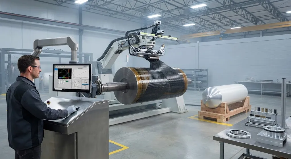
Manufacturing without a liner means the winding mandrel must be removable. Three approaches appear in development programs: wash-out mandrels of water-soluble polymer or plaster, which dissolve after cure; mechanically collapsible segmented mandrels; and inflatable bladders that deflate and withdraw through the boss bore. Wash-out mandrels dominate for cylindrical bodies because they leave no trace of material, though they add process steps and limit dome geometry.
Filament winding remains the default process, using high-modulus carbon fiber for stiffness and low fiber volume fraction targets tuned for permeability, not just strength. Wet winding with toughened epoxy is standard; some premium designs use prepreg tape winding or automated fiber placement (AFP) for dome reinforcement and boss regions where compaction is harder to control. Post-cure, every shell is proof-tested and screened by acoustic emission during pressurization to catch hidden microcrack formation.
Qualification Gap and Testing Requirements
The regulatory environment is the biggest near-term barrier. ISO 11119-3 and the EU TPED, along with FMVSS 304 for vehicle tanks, were all written for lined vessels; none yet covers linerless designs, though ISO's composite-vessel working groups are actively drafting Type V provisions. Until standards close, manufacturers qualify through bespoke test programs agreed case-by-case with national authorities.
A linerless qualification program must at minimum demonstrate:
- Permeation at rated pressure: steady-state hydrogen loss below regulatory thresholds, measured over weeks of dwell at service pressure and temperature.
- Pressure cycling: tens of thousands of fill-drain cycles proving microcracks stay isolated and never form a through-thickness network.
- Thermal cycling: for cryogenic tanks, repeated ambient-to-LH2 cycles validating matrix durability and boss seal integrity.
- Impact and damage tolerance: dropped-object and handling damage must not open a leak path, and damage must be detectable by inspection.
Until a harmonized standard exists, buyers should treat Type V claims with the same rigor they apply to any emerging pressure vessel technology: demand permeation data at service pressure, crack-isolation evidence from cycling tests, and transparency about which witnessed inspection authority reviewed the results.
Frequently Asked Questions
Why remove the liner at all if it does the permeation job so well?
The liner costs weight and introduces failure modes without adding structural strength. A Type IV polymer liner contributes several percent of total vessel mass, adds a bonded interface that can fail in fatigue, and complicates cryogenic service because the liner must stay flexible at -253°C. Removing it saves 10-15% of vessel mass — decisive in applications where hydrogen mass fraction is the purchasing metric — and eliminates liner-bond failure as a failure mode. The price is that everything the liner did, the composite wall and sealing architecture must now do alone, which is why linerless tanks demand tougher resins, tighter process control, and more thorough qualification than lined tanks.
How do linerless tanks keep hydrogen from leaking through the composite wall?
Three layers of defense work together. First, the matrix itself: toughened, high-strain epoxies shrink dramatically less during cryogenic cooldown, so fewer microcracks even start. Second, the laminate architecture: ply sequences are designed so that any crack is short, isolated, and never aligned with a through-thickness path, and internal barrier coatings — metallic, ceramic, or polymer films — block permeation at the inner surface. Third, process control: void content is held below roughly 1%, since voids are where leak networks nucleate. Together these measures bring laminate permeation within the same regulatory brackets used for lined tanks, validated by dwell testing at full service pressure.
When will Type V tanks be commercially available and certified?
A few demonstrator programs already run linerless vessels in test fleets and industrial gas applications, but certified series production is still ahead. The missing piece is a written standard: ISO and national regulators are drafting Type V provisions, and early adoption is likely through special-case approvals (such as individually certified tanks or limited demonstration fleets) before a harmonized rule lands. High-pressure rail and stationary storage programs are the most likely first movers because they can afford bespoke qualification; automotive and aviation follow once the standard closes. Buyers planning around Type V today should design their procurement to accept a qualification dossier rather than a standard certificate.
Conclusion
Type V linerless tanks represent the logical end state of pressure vessel evolution — a tank that is nothing but structure and containment, with no liner to add mass or fail. The engineering challenge is concentrated in three places: making the composite genuinely impermeable through resin, architecture, and coatings; sealing the boss directly to the laminate; and proving durability through cycling programs that regulators will accept. None of these are settled science, and all three are manufacturable today, which is why the technology is already appearing in demonstration fleets while standards catch up.
For tank manufacturers and hydrogen system integrators, the carbon fiber itself is the foundation of the linerless concept: grade, modulus, tow size, and surface treatment must be selected for a laminate that is simultaneously a structure and a barrier. Explore our high-performance carbon fiber products for pressure vessel applications, or contact our engineering team to discuss material selection and qualification support for your Type V tank program.
Part of topic
Related Articles
- Carbon Fiber Sheets for Sale: A Buyer Checklist for Thickness, Weave and Finish
- Carbon Fiber Plate Running Shoes: Manufacturing Process and Material Specifications
- Carbon Fiber Tubes for Sale: Spec Sheet Fields That Actually Matter
- Carbon Fiber Sheets Near Me: Local Dealers and Quick Turnaround Procurement
- Carbon Fiber Tubes Near Me: Local Stock Availability and Same-Day Delivery Options
- Carbon Fiber Plate Orthotic: Lightweight Prosthetic and Medical Device Applications