
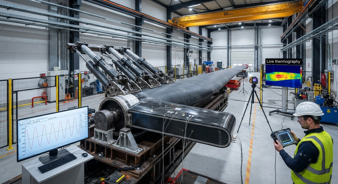
Technical guide to high-cycle fatigue (HCF) testing of carbon fiber composite wind turbine blades covering IEC 61400-23 certification requirements, ASTM D3479/D7774 constant-amplitude and spectrum loading protocols, S-N curve generation for carbon fiber/epoxy laminates, damage progression monitoring via acoustic emission and thermography, pass/fail criteria including stiffness degradation thresholds and residual strength verification, and statistical analysis using Weibull distribution for fatigue life prediction. Includes real test data tables and typical failure modes for carbon fiber spar caps and shear webs.
The Critical Role of Fatigue Testing in Blade Certification
Carbon fiber composites have become the material of choice for spar caps, shear webs, and root sections in modern multi-megawatt wind turbine blades. Rotor diameters now exceed 170 meters for offshore installations, with blade tips reaching 80–90 m/s, subjecting structures to complex cyclic loading that accumulates 10⁷ to 10⁸ cycles over a 20–25 year design life. High-cycle fatigue (HCF) — loading above 10⁴ cycles with stress amplitudes below the yield point — is the dominant failure mechanism for these large composite structures. Unlike metals with distinct fatigue limits, carbon fiber composites show a continuously decreasing S-N response with no clear endurance limit, making standardized fatigue testing essential for IEC 61400-23 certification.
With global wind capacity exceeding 900 GW and blade replacement costs of $200,000–$1.5 million per offshore unit, fatigue-induced blade failures accounted for 14% of all wind turbine structural incidents between 2019 and 2025, with average downtime of 45 days per event. For carbon fiber blade manufacturers and B2B composite suppliers, accredited HCF testing is both a certification requirement and a critical risk management tool.
Applicable Standards and Testing Protocols
Carbon fiber blade HCF certification is governed by a hierarchy of international standards:
| Standard | Scope | Test Type | Key Requirements for Carbon Fiber |
|---|---|---|---|
| IEC 61400-23 | Full-scale blade structural testing | Cyclic loading (10⁶–10⁷ cycles, flapwise and edgewise) | Min. 10⁶ cycles; max stiffness degradation 5%; no visible damage before 80% of target cycles |
| ASTM D3479 | Constant-amplitude tension-tension fatigue of composites | Coupon (250×25×2 mm), R=0.1, 5–10 Hz | Stress at 30–80% of UTS; min. 5 specimens per level; run-out at 10⁷ cycles |
| ASTM D7774 | Flexural fatigue of composites | 4-point bending (150×25×4 mm), 3–8 Hz | Modulus retention ≥ 85% at run-out; relevant for shear web laminates |
| ISO 13003 | Cyclic fatigue of fiber-reinforced plastics | Coupon to component-level framework | Max 10 Hz to avoid hysteretic heating; min. 10 valid specimens |
| DNV-ST-0376 | Composite blade design and certification | Sub-element spar cap and shear web (up to 3 m) | Residual strength ≥ 90% of initial UTS after spectrum loading |
For B2B carbon fiber suppliers targeting wind energy, ASTM D3479 coupon testing is the minimum for material qualification. However, leading OEMs — Vestas, Siemens Gamesa, Goldwind — increasingly demand sub-element and component-level fatigue data per DNV-ST-0376, as coupon data alone does not capture thick laminate scaling or bond line stress concentrations present in full-scale blades.
S-N Curve Generation for Carbon Fiber/Epoxy Laminates
The fatigue behavior of carbon fiber/epoxy composites follows a power-law S-N decay without a distinct fatigue limit. Representative data for standard-modulus unidirectional laminates (60% fiber volume fraction) used in spar caps:
| Max Stress (% UTS) | Stress Amplitude (MPa) at R=0.1 | Median Cycles to Failure (N₅₀) | Failure Mode |
|---|---|---|---|
| 80% | 648 | 2.3 × 10³ | Fiber fracture with longitudinal splitting |
| 70% | 567 | 1.8 × 10⁴ | Fiber breakage clusters, matrix cracking |
| 60% | 486 | 1.5 × 10⁵ | Matrix cracking at fiber/matrix interface |
| 50% | 405 | 8.2 × 10⁵ | Distributed matrix cracks, incipient delamination |
| 45% | 365 | 3.1 × 10⁶ | Matrix microcracking, stiffness loss ≤ 8% |
| 40% | 324 | 1.2 × 10⁷ (est.) | No visible damage; stiffness retention > 92% |
Data: T700-grade CF/epoxy, 60% FVF, R=0.1, 8 Hz, 23°C. Fatigue strength ratio (stress at 10⁶ cycles / UTS) is approximately 0.45–0.50, significantly exceeding E-glass/epoxy at 0.25–0.35.
Damage Monitoring and Pass/Fail Criteria
IEC 61400-23 and DNV-ST-0376 specify three complementary real-time monitoring techniques. Acoustic emission (AE): Piezoelectric sensors at the spar cap midpoint and shear web junction track AE hit rate. An increase by a factor of 5 or more over baseline indicates significant damage onset. Stiffness degradation: The primary pass/fail criterion — global blade stiffness, measured as load-deflection slope at the tip, must not degrade more than 5% during full-scale fatigue tests. For carbon fiber spar cap sub-elements, 10% stiffness loss defines technical failure. Thermography: Infrared cameras detect localized hysteretic heating; a temperature rise exceeding 10°C above ambient indicates damage accumulation. Tests must pause if any point exceeds 60°C surface temperature to prevent resin degradation.
Statistical Analysis and Acceptance Criteria
Carbon fiber fatigue data exhibits significant scatter — typically one to two orders of magnitude in cycle count at a given stress level. Standards require a two-parameter Weibull distribution for characterization. The acceptance criterion for blade material qualification is that the B₁₀ life (10% failure probability) at the design stress level must be at least ½ times the target fatigue life. For example, if the design requires 10⁷ cycles at 40% UTS, the B₁₀ life must be ≥ 5 × 10⁶ cycles, requiring a minimum of 12–15 valid tests per stress level for 90% confidence estimation.
Common Fatigue Failure Modes
Based on published blade test data (2018–2025), the most common fatigue failure modes in carbon fiber wind blades are: spar cap delamination at ply drop locations (34% of failures), adhesive joint failure between spar cap and shear web (28%), buckling-induced delamination of the compression-side spar cap (18%), trailing edge adhesive joint separation (12%), and root connection bolt fatigue (8%).
Frequently Asked Questions
What is the difference between HCF and LCF for carbon fiber blades?
High-cycle fatigue (HCF, 10⁴–10⁸ cycles) is the dominant regime for normal wind operation, involving stress amplitudes below yield with progressive microcrack accumulation. Low-cycle fatigue (LCF, < 10⁴ cycles) applies to extreme events like storm loading or emergency shutdown, characterized by widespread matrix cracking at 50–80% of UTS. Blade certification requires both regimes to be tested: LCF through extreme load spectrum loading (50–200 cycles for storm events) and HCF through operational load spectrum (10⁶–10⁷ cycles for normal operation).
How does carbon fiber fatigue compare to glass fiber in blades?
Carbon fiber composites significantly outperform E-glass: (1) Fatigue strength ratio — carbon fiber achieves 0.45–0.50 versus glass at 0.25–0.35. (2) S-N curve slope — carbon fiber shows 6–10% strength reduction per decade versus 12–18% for glass, meaning the relative gap widens at higher cycles. (3) Stiffness retention — carbon fiber retains 90–95% of initial stiffness at 10⁷ cycles compared to 75–85% for glass. (4) Specific fatigue strength — carbon fiber is 3–4 times higher than glass. The primary disadvantage is cost: carbon fiber spar caps increase blade material cost by 30–60%, offset by 15–25% blade mass reduction and lower tower/foundation costs offshore.
What are the most common fatigue test failure modes in carbon fiber blades?
The five most common modes from industry data (2018–2025) are: (1) Spar cap delamination at ply drop locations (34%) — interlaminar stress concentrations where the number of plies steps down along the span. (2) Adhesive joint failure between spar cap and shear web (28%) — peel and shear stresses degrading the bond line. (3) Compression-side spar cap buckling-induced delamination (18%) — thin-walled laminate buckling under flapwise loading causing ply separation. (4) Trailing edge adhesive joint separation (12%) — damage from edgewise vibration modes. (5) Root connection bolt/bushing fatigue (8%) — high mean stress in metallic inserts at the hub connection.
Part of topic
Related Articles
- Bio-Based Carbon Fiber Precursors: Lignin and Polyethylene for Low-Cost Production
- Large-Tow Carbon Fiber Cost Analysis: 48K vs 60K Price-Performance Comparison
- Carbon Fiber-Resin Interface Bonding: Surface Treatment and Coupling Agent Optimization
- Digital Twin for Carbon Fiber Manufacturing: Real-Time Process Monitoring and Defect Prevention
- Thermoplastic Carbon Fiber Welding for Automotive: Ultrasonic and Induction Welding Process Windows
- Large-Tow Carbon Fiber Wet Spinning: Process Optimization for 48K/60K Production Efficiency