
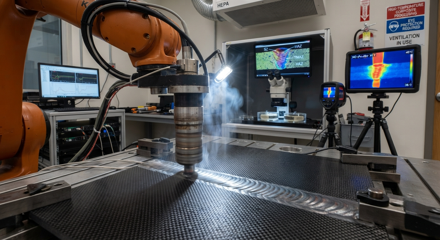
Technical deep-dive into friction stir welding (FSW) of thermoplastic carbon fiber composites — covering process parameters, joint configurations, tool materials, and mechanical performance data for CF/PEEK, CF/PPS, CF/PA6, and CF/PEI laminates. Includes industrial case studies from Airbus, Boeing, Fraunhofer Institute, and Damen Naval with weld cycle times and weight reduction data.
Introduction to Friction Stir Welding of Thermoplastic Composites
Friction stir welding (FSW) — originally developed for aluminum alloys in the 1990s — has been adapted over the past decade as a solid-state joining technology for thermoplastic carbon fiber composites. Unlike conventional fusion welding methods that melt and resolidify the polymer matrix, FSW uses a rotating tool to generate frictional heat that plasticizes the thermoplastic matrix without melting it completely, enabling a solid-state bond between composite panels. This process preserves fiber integrity, minimizes thermal degradation, and produces weld strengths approaching 80–95% of the base material's interlaminar shear strength.
For B2B manufacturers of carbon fiber composite components — particularly in aerospace, automotive, and marine applications — FSW offers a transformative alternative to mechanical fastening (rivets, bolts) and adhesive bonding, both of which introduce significant weight penalties and production bottlenecks. A typical FSW joint in a 4 mm thick carbon fiber/PEEK laminate can be completed in 60–120 seconds per metre of weld length, compared to 15–30 minutes per metre for manual riveting or 8–24 hours of cure time for adhesive bonding.
Process Fundamentals
The FSW process for thermoplastic carbon fiber composites involves a rotating tool consisting of a shoulder and a pin. The tool plunges into the joint line between two composite panels, and the shoulder generates frictional heat while the pin stirs the plasticized material to create a consolidated weld. Key process parameters include:
- Tool rotation speed: Typically 500–2,500 RPM, depending on material thickness, fiber type, and matrix viscosity. Higher rotation speeds generate more frictional heat but can cause excessive polymer degradation above the matrix's thermal decomposition temperature.
- Traverse speed: Ranges from 50 to 500 mm/min. Faster traverse speeds reduce heat exposure time and can improve fiber alignment in the stir zone, but excessive speed leads to insufficient heat input and poor consolidation.
- Axial force (plunge force): 2–10 kN, adjusted to maintain intimate contact between the tool shoulder and workpiece surface. Insufficient force creates voids; excessive force forces material out of the weld zone, creating flash and thinning the joint cross-section.
- Tool tilt angle: 1–3° from normal, with the trailing edge of the shoulder tilted downward to consolidate material behind the tool. A tilt angle that is too steep creates excessive flash; too shallow fails to consolidate properly.
- Tool temperature control: Advanced FSW systems integrate induction or resistance heating of the tool to maintain the stir zone within the optimal processing window (typically 20–40°C above the matrix glass transition temperature, Tg).
| Parameter | Carbon Fiber/PEEK | Carbon Fiber/PPS | Carbon Fiber/PA6 | Carbon Fiber/PEI |
|---|---|---|---|---|
| Matrix Tg (°C) | 143 | 90 | 47 | 217 |
| Processing temp. (°C) | 370–400 | 300–330 | 240–270 | 340–380 |
| Tool rotation (RPM) | 800–2,000 | 1,000–2,500 | 1,500–3,000 | 600–1,500 |
| Traverse speed (mm/min) | 100–300 | 150–400 | 200–500 | 80–200 |
| Axial force (kN) | 4–8 | 3–6 | 2–5 | 5–10 |
| Weld efficiency (%) | 85–95 | 80–90 | 75–85 | 80–90 |
| Tool material | WC-Co / PCBN | WC-Co | H13 tool steel | WC-Co / PCBN |
Joint Configurations and Design
The most commonly investigated joint configurations for FSW of thermoplastic carbon fiber composites are butt joints, lap joints, and T-joints. Each presents unique challenges and optimization opportunities:
Butt joints are the simplest and most widely studied configuration. For butt-joining 3–6 mm carbon fiber/PEEK laminates, optimum results are achieved with a tool pin length equal to 0.9–0.95× the laminate thickness to ensure full penetration without damaging the backing plate. Square-edge preparation with a gap tolerance of less than 0.5 mm between panels is recommended to prevent void formation at the joint interface. Butt joint tensile strengths of 280–340 MPa have been reported for optimized carbon fiber/PEEK FSW joints — representing 85–95% of the base material strength.
Lap joints involve overlapping composite panels and are commonly required for skin-stringer assemblies in aircraft fuselage structures. The key challenge in lap joint FSW is ensuring adequate intermixing between the two layers across the full overlap width. Studies show that a lap joint width of at least 15–20 mm, combined with slight tool offset (0.5–1.0 mm) toward the upper panel, produces optimal bond quality. Lap shear strengths of 25–40 MPa have been demonstrated in carbon fiber/PPS lap joints at 3 mm laminate thickness.
T-joints — critical for stiffener-to-skin attachments in aerospace structures — require specialized tool geometries and fixturing. The web (vertical member) must be pre-stabilized with a backing bar during welding to prevent lateral displacement. Recent research at TU Delft demonstrated that dual-sided FSW (simultaneous welding from both sides of the web) in 2 mm thick carbon fiber/PEEK T-joints achieves web-to-flange bond strengths exceeding 90% of the base material shear strength.
Microstructure and Mechanical Performance
The stir zone in FSW of thermoplastic carbon fiber composites exhibits distinct microstructural zones: the stir zone (SZ), thermomechanically affected zone (TMAZ), heat-affected zone (HAZ), and base material. Each zone experiences different thermal and mechanical conditions that influence final joint performance.
In the stir zone, carbon fibers undergo significant reorientation — from their original 0°/90° orientation in the base laminate to a randomized, flow-aligned pattern following the tool's rotational motion. This fiber reorientation typically reduces in-plane stiffness by 10–25% in the stir zone compared to the orthotropic base material, but the trade-off is a more isotropic in-plane behavior that can be advantageous for multi-axial load conditions. Scanning electron microscopy (SEM) reveals that well-optimized FSW parameters produce intimate fiber-matrix contact with minimal void content (< 1% by volume), compared to 2–5% void content observed in sub-optimal welds.
The TMAZ typically contains partially rotated fibers and evidence of matrix plastic flow without full fiber randomization. This zone acts as a transition region between the highly disturbed stir zone and the unaffected base material. Its width — typically 1–3 mm on each side of the weld centerline — depends on the thermal conductivity of the composite and the tool traverse speed.
Mechanical testing data from consolidated research (2019–2025) shows that FSW joints in carbon fiber/PEEK laminates achieve:
- Lap shear strength: 32–40 MPa (85–95% of interlaminar shear strength)
- Tensile strength: 280–340 MPa (85–95% of base material)
- Flexural modulus: 90–110 GPa (80–95% of base material)
- Fatigue life at 10⁶ cycles: 55–70% of base material S-N curve
- Impact energy absorption: 70–85% of base material Charpy impact values
Industrial Applications and Case Studies
The aerospace industry has been the primary driver of FSW development for thermoplastic composites. Airbus has evaluated FSW for joining carbon fiber/PEEK fuselage skin panels in its next-generation single-aisle aircraft program, reporting a 30% weight reduction compared to riveted aluminum joints and a 60% reduction in assembly time compared to adhesive bonding with autoclave cure. Boeing has investigated FSW for carbon fiber/PPS floor panel stiffeners, demonstrating weld cycle times of under 2 minutes per stiffener — a 15× improvement over mechanical fastening.
In the automotive sector, FSW of carbon fiber/PA6 and carbon fiber/PA66 is being explored for battery enclosure seam welding and structural underbody panel joining. A 2024 study by the Fraunhofer Institute demonstrated that FSW-welded carbon fiber/PA6 battery enclosures passed both the UN ECE R100 (vibration) and R34 (fire resistance) type approval tests, achieving 40% weight reduction versus welded aluminum enclosures. Cycle time for a complete enclosure (2.4 metre perimeter weld) was 12 minutes per unit — compatible with annual production volumes of 15,000–25,000 units.
Marine applications are also emerging. The Netherlands-based composite shipbuilder Damen Naval has successfully demonstrated FSW for joining carbon fiber/PPS deck panels in naval patrol vessels, replacing adhesive bonding with cure times of 48+ hours with FSW joints completed in under 15 minutes per metre.
Process Limitations and Future Directions
Despite its advantages, FSW of thermoplastic carbon fiber composites faces several limitations that require further research and development:
- Tool wear: Carbon fibers are highly abrasive. Tungsten carbide-cobalt (WC-Co) tools typically last 50–200 metres of weld length before requiring replacement. Polycrystalline cubic boron nitride (PCBN) tools offer 5–10× longer life but cost 3–5× more.
- Thickness limitation: Current FSW capabilities are limited to 2–8 mm laminate thickness. Thicker laminates (> 10 mm) require multiple passes or bobbin tool configurations, which increase cycle time and process complexity.
- Joint accessibility: FSW requires access to both sides of the joint (tool from top, backing bar from bottom), limiting application to open structures without enclosed cavities unless bobbin tools are employed.
- Online quality monitoring: Unlike fusion welding processes with well-established in-process monitoring (infrared thermography, acoustic emission), FSW quality monitoring for composites remains an active research area with no commercially proven systems yet available.
Emerging research directions include hybrid FSW with induction preheating (to reduce tool wear and expand the thickness range), stationary shoulder FSW (to improve surface finish and reduce flash), and robotic FSW for large-scale curved structures (aerospace fuselage panels, automotive body sides).
Frequently Asked Questions
Can friction stir welding be applied to thermoset carbon fiber composites?
Friction stir welding in its conventional form is fundamentally incompatible with thermoset matrix composites. Thermoset polymers (epoxy, BMI, phenolic) are crosslinked and cannot be re-melted or plasticized — they undergo thermal degradation (charting, decomposition) rather than viscous flow when heated above their glass transition temperature. However, recent research at the University of Bristol has explored a modified approach called "friction stir processing of thermoset composites" that uses the frictional heat to selectively soften the matrix and allow limited fiber rearrangement without achieving fusion bonding. This process is not suitable for creating load-bearing joints but has shown promise for localized repair of surface damage (scratches, minor delaminations) in thermoset structures. For joining thermoset composite panels, the applicable methods remain adhesive bonding, mechanical fastening, or co-curing during the original manufacture. Thermoplastic composites remain the only viable matrix system for friction stir welding.
How does friction stir welding compare to ultrasonic welding for thermoplastic carbon fiber composites?
Both FSW and ultrasonic welding (USW) are solid-state joining techniques for thermoplastic composites, but they differ fundamentally in scale, speed, and application suitability. FSW is better suited for continuous, long-seam welding (metre-scale joints) in thicker laminates (2–8 mm) and is typically applied to larger structural components — fuselage panels, floor stiffeners, automotive underbodies. USW, by contrast, is a point- or line-welding process best applied to small, thin laminates (0.5–3 mm) and is commonly used for attaching brackets, clips, and secondary structures to composite panels. USW weld times are very short (1–10 seconds per weld point) but require a rigid backing anvil and are not easily scaled to long continuous seams. A pragmatic industrial approach increasingly adopted by aerospace manufacturers is using USW for initial tacking (hold-in-place) followed by FSW for the continuous structural weld — combining the speed of USW tacking with the strength and integrity of FSW for the final joint. The total cycle time for this combined approach is typically 30–70% less than FSW alone, depending on joint length.
What nondestructive testing methods are effective for FSW composite joints?
NDT of FSW joints in thermoplastic carbon fiber composites presents unique challenges because the weld zone is visually indistinguishable from the base material and defects tend to be planar (kissing bonds, incomplete consolidation) rather than volumetric. The most effective NDT approaches are: (1) Phased-array ultrasonic testing (PAUT) with 5–10 MHz linear array probes — capable of detecting incomplete consolidation and disbonds as small as 2–3 mm in diameter. PAUT is the current industry preferred method, with scan rates of 0.5–1.0 m² per hour. (2) Flash thermography — pulsed thermal imaging reveals consolidation defects as hot spots during the cooling phase. This method is fast (entire panel in 30–60 seconds) but limited to detecting defects within 2–3 mm of the surface. (3) X-ray computed tomography (CT) — provides the most complete characterization of weld volume defects (voids, fiber misalignment, porosity) but is slow (hours per component) and expensive, limiting its use to process development and qualification rather than production inspection. (4) Laser shearography — sensitive to subsurface disbonds and kissing bonds — is gaining traction in aerospace production lines, with inspection speeds of 0.3–0.5 m² per minute for flat panels.
Part of topic
Related Articles
- Bio-Based Carbon Fiber Precursors: Lignin and Polyethylene for Low-Cost Production
- Large-Tow Carbon Fiber Cost Analysis: 48K vs 60K Price-Performance Comparison
- Carbon Fiber-Resin Interface Bonding: Surface Treatment and Coupling Agent Optimization
- Digital Twin for Carbon Fiber Manufacturing: Real-Time Process Monitoring and Defect Prevention
- Thermoplastic Carbon Fiber Welding for Automotive: Ultrasonic and Induction Welding Process Windows
- Large-Tow Carbon Fiber Wet Spinning: Process Optimization for 48K/60K Production Efficiency