
Most engineering materials used for structural parts — aluminum alloys excepted — are electrical insulators. Carbon fiber is the remarkable exception: its graphitic microstructure conducts electrons along the fiber direction with a resistivity low enough to qualify as a conductor. A sta
Introduction
Most engineering materials used for structural parts — aluminum alloys excepted — are electrical insulators. Carbon fiber is the remarkable exception: its graphitic microstructure conducts electrons along the fiber direction with a resistivity low enough to qualify as a conductor. A standard carbon fiber has an electrical resistivity of roughly 1.5×10⁻⁵ to 1.8×10⁻⁵ Ω·m along the filament, several orders of magnitude lower than the ~1×10⁵ Ω·m of a neat epoxy resin. This single property changes the design space entirely: a carbon fiber laminate can carry currents, shield electromagnetic interference, and manage lightning strike energy while still performing its primary structural duty.
For electronics manufacturers, the payoff is a structural material that replaces separate metal shields, conductive gaskets, and ground planes. For aerospace engineers, conductivity is the key to managing lightning strikes on a composite airframe. This article explains the electrical engineering of carbon fiber composites — how conductivity is built, measured, and engineered into multifunctional structures.
Why Carbon Fiber Is Conductive
The electrical behavior of a carbon fiber comes from its turbostratic graphite microstructure: sp²-bonded carbon sheets stacked in a partially ordered lattice, with delocalized electrons free to travel along the graphitic planes. Because the planes are aligned with the fiber axis in a high-modulus fiber, conductivity along the length can reach 5.9×10⁴ S/m, while transversely the fiber relies on inter-filament contact and matrix properties and drops many orders of magnitude.
In a laminate this anisotropy has three consequences designers must respect:
- Directionality: In-plane conductivity is high along the fiber direction and low perpendicular to it. Unidirectional panels are strongly anisotropic conductors; quasi-isotropic stacks are comparatively more balanced.
- Inter-lamina resistance: Ply-to-ply conduction occurs through fiber-to-fiber contact and resin-rich interfaces, adding electrical resistance at each interface. The apparent laminate conductivity is always lower than the fiber's intrinsic value.
- Through-thickness weakness: The Z-direction conductivity is typically 10³-10⁶ times lower than the in-plane value, which governs edge glow and areas where current must cross the thickness.
Engineering Conductivity for Shielding
EMI shielding effectiveness (SE) is the sum of reflection, absorption and internal multiple reflection losses. For electrically thin shields the reflection term dominates at low frequencies; as frequency rises, absorption increases and becomes significant for a conductive structure.
Designers manipulate three levers in carbon fiber laminates:
- Fiber architecture: woven fabrics, unidirectional ply stacks, and symmetric layups alter the balance of in-plane conductivity. Higher fiber volume fraction with well-consolidated plies lowers inter-lamina resistance.
- Conductive matrix systems: silver-, nickel-, or graphene-loaded epoxy, or silver-plated carbon fibers, are used when bulk conductivity must be raised. Loadings of 5-20% of conductive fillers raise volume conductivity by 3-5 orders of magnitude.
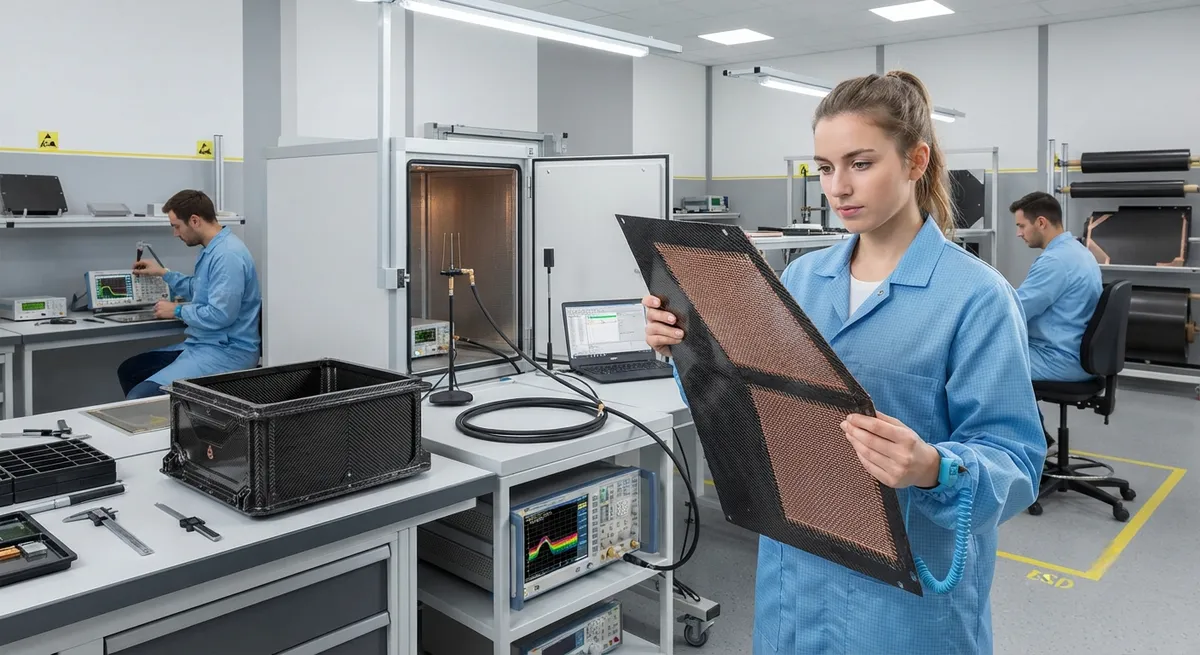
- Surface metallic layers: copper or aluminum meshes, foil laminates, or plated coatings applied to the outer ply give performance near solid metal while keeping the composite structure intact.
The table below compares representative shielding effectiveness values at 1 GHz for structures of typical thickness:
| Material / Structure | Surface/Bulk Resistivity | SE at 1 GHz (dB) | Typical Use |
|---|---|---|---|
| Solid aluminum sheet (1.5 mm) | 2.7×10⁻⁸ Ω·m | 90-100 | Reference enclosure |
| CFRP laminate, standard epoxy (2 mm, quasi-isotropic) | ~10⁻² Ω·m (in-plane) | 25-40 | General enclosures |
| CFRP + bronze/copper mesh (expanded foil) | Near-metallic surface | 60-85 | Aerospace & defense housings |
| CFRP with nickel-plated carbon fiber fabric | 10⁻⁴-10⁻³ Ω·m | 50-70 | Marine-electronics enclosures |
| Metal-impregnated matrix (sprayed coating) | 10⁻⁴-10⁻³ Ω·m | 45-60 | Retrofit shield cost-optimization |
As the figures show, a bare CFRP enclosure is a moderate shield (25-40 dB blocks up to 99% of incident energy), usually insufficient for strict EMI standards such as MIL-STD-461; the leap to 60+ dB requires a metallic external conductive layer or conductive fillers in the matrix.
EMI Shielding in Electronics Enclosures
For electronics manufacturers, carbon fiber enclosures are interesting because they solve several problems at once: EMI protection, structural strength, and weight. Practical guidance for enclosure design:
- Maintain electrical continuity: mating surfaces, covers, and seams must be joined with conductive gaskets or continuous bonding to avoid the seam aperture problem where long seams radiate like slot antennas.
- Ground the structure: the enclosure shall be bonded to the equipment chassis ground with low-resistance conductive straps.
- Design the aperture budget: every opening (vents, connectors, displays) acts as a radiating aperture; mesh-covered vents and gasketed connector cutouts keep the effective SE high.
- Pair with metal parts: the highest-value configurations pair carbon fiber covers with metal frames or internal ground planes, gaining both EMI performance and stiffness.
The composite advantage is measured: a carbon fiber enclosure with a copper mesh layer typically achieves 60-85 dB SE while being 30-50% lighter than the equivalent aluminum enclosure.
Lightning Strike Protection for Aircraft
Lightning protection is one of the most consequential applications of conductivity in carbon fiber. An aircraft airframe can be struck by lightning 2-10 times per year; a direct strike injects up to 200 kA peak current distributed among conduction paths with extremely fast rise times and significant energy deposition.
Unprotected CFRP is a poor conductor compared to aluminum airframes: aluminum conducts current away quickly; CFRP, with conductivity four orders of magnitude lower, concentrates resistive heating around the attachment point, sublimating resin and damaging the laminate. The industry standard engineering solution arranges conductive structural layers:
- Expanded copper foil (EFB) or copper mesh: co-cured onto the outer surface of the laminate, acting as the primary zone of the strike handling 1-10 kA blows, keeping the composite below damage thresholds.
- Conductive film materials: woven wire mesh products and aluminum screens applied between outer plies.
- Conductive coatings: on thin skins, sprayed metal or conductive paints provide fast current paths.
The design target is to keep zone 2 (beyond the strike attachment) within repair limits and zone 1 (attachment) repairable — matching the envelope established by test standards such as SAE ARP 5412 ARP 5416.
Multifunctional Structures
The same conductivity that shields and conducts lightning also creates a host of structural-with-electrical functions:
- Structural grounding: the laminate itself acts as a ground plane, eliminating separate copper braid in many closed enclosures.
- Sensor and health-monitoring arrays: resistance changes in carbon plies can be read to detect damage in structural health monitoring systems.
- De-icing and anti-icing: Joule heating of resistive carbon layers melts ice on aircraft leading edges and nacelles.
- Antennas integrated into structure: conductive plies are shaped into patches, slots, or VHF antennas molded into the skin.
- EMI gaskets and seals: conductive elastomer gaskets and foam routes close the gaps between conductive composite parts.
Each function adds design constraints — resistivity targets, thermal budget, weight — and needs to be traded against the mechanical design, exactly like any other system requirement.
Frequently Asked Questions
How conductive is a carbon fiber composite compared with a metal?
The in-plane resistivity of a commercial CFRP laminate is on the order of 10⁻² Ω·m versus 2.5×10⁻⁸ Ω·m for copper — about 5-6 orders of magnitude lower conductivity. Above this, the through-thickness resistivity is typically 10³-10⁶ times higher and conductivity is much less consistent. In practice, a bare CFRP behaves as a moderate shield, blocking most radiated interference below ~40 dB, while plain metal shields reach 90 dB+.
Is EMI shielding the same as lightning strike protection in carbon fiber structures?
No — they are different electrical requirements. EMI shielding is a continuous, low-current requirement: the enclosure must attenuate interference across a wide frequency band (typically 30 MHz to 40 GHz for electronics) using moderate, uniformly distributed conductivity with good continuity between mating parts. Lightning strike protection is a transient, extremely high-current event: a direct strike injects up to 200 kA through the structure, and the design must route that pulse without structural or electrical failure. Lightning protection therefore demands deliberate high-current paths — expanded foil mesh, bonded lugs, and fast-rise-time attachments rated for the pulse — while shielding needs only consistent moderate conductivity. Both use conductivity, but the engineering is entirely different.
Can carbon fiber composites replace all metal shielding and ground planes?
For many fixed and commercial applications, yes: enclosures in aviation, marine electronics, and industrial equipment increasingly use conductive composites. But a pure CFRP laminate without a conductive mesh or filler reaches only 25-40 dB of shielding; strictly EMC-compliant housings (military, medical, railway) almost always pair the carbon skin with a conductive mesh or foil layer, or a metal ventilation grate and fastening plan. The modern answer — CFRP for structure plus a thin conductive layer for EMC — delivers both weight savings and compliant performance.
How does lightning travel through a painted carbon fiber skin?
The strike current must be routed through the attachment zone by conductive lightning protection layers — copper mesh or foil co-cured into the laminate immediately below the paint. Paint has far too little conductivity to carry lightning-scale current, so the protective layer conducts the charge while the paint remains intact by allowing the current to spread below the surface. The metallic or carbon plane under the paint carries the current away toward the frame lugs, keeping voltage gradients low and damage localized, which is exactly the arrangement used in modern composite airframes.
Conclusion
Conductivity is the property that converts carbon fiber from a passive structural material into the backbone of multifunctional systems: electromagnetic shields for electronics, lightning paths for aircraft, and grounding planes for entire assemblies. Getting the engineering right — continuity, interface resistance, surface layers — turns existing design shortcuts into controllable performance parameters.
Whether you are making electronic enclosures, EMI-critical cabinets, or composite fuselage, the first step is measuring your fiber type, layup, and interface resistance together. YongXian supplies carbon fiber fabrics, prepregs, and conductive aerospace materials with matched engineering data. Explore our carbon fiber product range or contact our engineering team to discuss conductive composite qualification for your program.
Part of topic
Related Articles
- Filament Wound Epoxy Tubing: Selection Guide for Industrial and Aerospace Applications
- Filament Wound Epoxy Tubes Advantages: Over Metal and Pultruded Alternatives
- Carbon Fiber Tube Strength: Analysis Methods and Design Allowables
- Filament Wound Epoxy Tubes: Mechanical Properties and Material Data Sheets
- Carbon Fiber Drone Blades and Propellers: Stiffness, Balance and Noise Reduction
- Fiberglass Filament Wound Tubes: Cost-Effective Alternative to Carbon Fiber
Interested in Our Products?
Contact our team for competitive pricing and technical specifications.
Get a QuoteRelated Products

Carbon fiber standard plate-3k stripe
Lightweight, ultra-rigid standard sheets for drone fuselages, robot housings, facades and structural applications.

Carbon Fiber Plate — 3K Twill T700 3.0mm
Medium-thickness 3.0mm carbon fiber plate offering significantly higher load capacity while maintaining attractive 3K twill finish. Suitable for structural brackets, reinforcement plates, and load-bearing panels.

Custom Carbon Fiber Medical Device Components
Medical-grade carbon fiber components manufactured for imaging equipment, surgical instruments, and patient support systems. Carbon fiber's radiolucency (X-ray transparency) and high strength-to-weight ratio make it ideal for CT scanner beds, wheelchair frames, surgical robot arms, and MRI-compatible accessories. Biocompatible resin systems available.

Carbon Fiber Plate — 3K Twill T700 1.5mm
Thin 1.5mm carbon fiber plate with 3K twill weave surface. Lightweight and stiff, commonly used for covers, panels, drone bodies, and applications requiring a premium aesthetic appearance.

Carbon Fiber Fishing Rod Blank
High-quality carbon fiber fishing rod blank manufactured from multiple grades of Toray carbon fiber cloth. Available in a wide range of lengths, powers, and actions for freshwater and saltwater applications. Suitable for OEM rod building.