
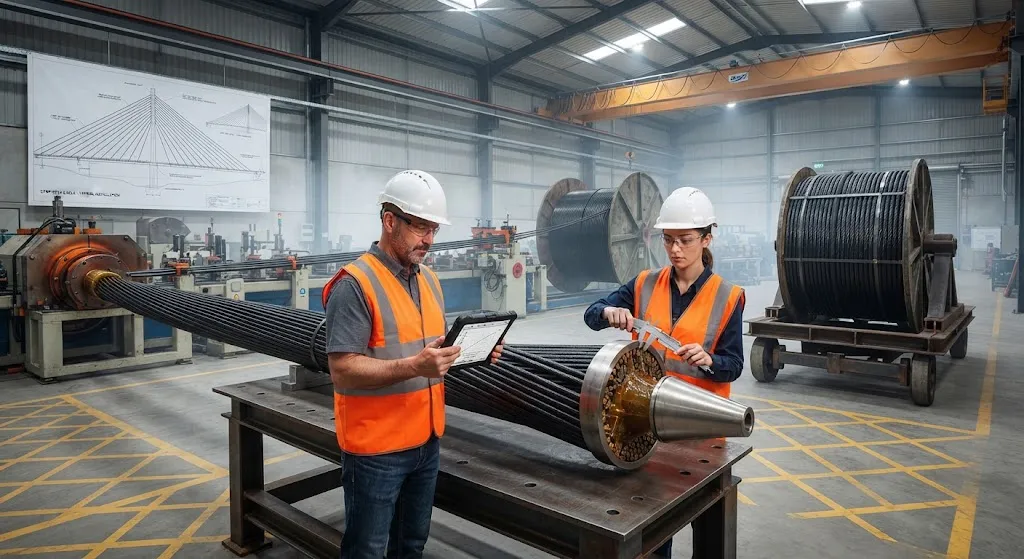
Every cable-stayed bridge is held up by its stay cables: high-strength steel strands that carry the deck through inclined tension members to the towers. Steel has served this role for more than half a century, but it brings two persistent liabilities. Corrosion attacks the strands throu
Introduction
Every cable-stayed bridge is held up by its stay cables: high-strength steel strands that carry the deck through inclined tension members to the towers. Steel has served this role for more than half a century, but it brings two persistent liabilities. Corrosion attacks the strands through the sheath, especially at the anchorages where moisture collects, and fatigue loads from traffic and wind accumulate cycle after cycle on the same tendon. Replacing a stay cable on an operating bridge is a major operation — lane closures, temporary supports, and costs that can reach millions of dollars.
Carbon fiber reinforced polymer (CFRP) stay cables eliminate both failure mechanisms at their source. Carbon fiber does not corrode, and it exhibits fatigue endurance far beyond that of steel under equivalent cyclic loading. Its specific strength — strength divided by density — is roughly five times that of steel wire, which opens new possibilities for very long spans where cable weight becomes the limiting factor. This article reviews the engineering of CFRP stay cables, the anchoring systems that make them practical, and the data that define their long-span feasibility.
Why Steel Stay Cables Need Replacing
Steel stay cable systems manage corrosion through layered defense: galvanized or epoxy-coated strands, a polyethylene sheath, and in modern systems, a dehumidified air environment inside the sheath. When any layer is compromised — a damaged sheath at a wind-induced vibration point, a failed joint seal, or water ingress at the anchorage — corrosion begins and accelerates. Inspection findings across aging cable-stayed bridges consistently identify anchorage corrosion as the dominant deterioration mode, and the repair is invasive because the entire tendon force must be transferred before a strand can be replaced.
Fatigue compounds the problem. Stay cables experience large stress ranges from live loads and dynamic wind effects, and the steel strands accumulate fatigue damage at the anchorage where the gripping mechanism introduces local stress concentrations. Design codes therefore limit the working stress in steel stay cables to a fraction of their ultimate strength — commonly around 40-45% — to keep fatigue life acceptable. CFRP changes this calculus: its fatigue limit is a much higher proportion of ultimate strength, so a CFRP cable can be designed to a higher utilization ratio while retaining fatigue margin.
How CFRP Stay Cables Work
A CFRP stay cable is built from parallel carbon fiber strands or rods embedded in an epoxy matrix, bundled into the required cross-section, and terminated at each end in an anchorage. The material properties that matter for cable design are the tensile strength and modulus along the cable axis, which are achieved with unidirectional fiber alignment — 60-65% fiber volume fraction in production pultruded rods. Typical CFRP cable rods deliver 2,400-2,600 MPa ultimate tensile strength with a modulus of 140-160 GPa; by comparison, prestressing steel strand offers 1,860-2,160 MPa strength at 195-205 GPa modulus.
The decisive advantage is specific strength. Steel wire at 1,860 MPa strength and 7.85 g/cm³ density offers about 237 MPa per g/cm³; CFRP at 2,500 MPa and 1.6 g/cm³ offers about 1,560 MPa per g/cm³ — a factor of roughly 6.5. For a given design load, a CFRP cable weighs about one-fifth of an equivalent steel cable. This matters twice over: the cable carries less of its own weight, freeing capacity for deck load, and the tower and anchorage structures support a lighter cable system.
Long-span feasibility follows directly. In a cable-stayed bridge, the cable's own weight is a load the cable must carry, and beyond a certain span the cable weight becomes a meaningful fraction of the total. For spans beyond roughly 1,000 m, the self-weight advantage of CFRP becomes decisive — it is one of the enablers for pushing cable-stayed spans toward and beyond the current records, where steel cables would dominate the load budget.
Anchoring: The Critical Design Problem
Carbon fiber's anisotropic strength is both its advantage and its challenge at the anchorage. The same unidirectional construction that delivers outstanding axial strength offers weak transverse properties, so a conventional wedge grip that bites into steel strands would crush or split a CFRP rod. The anchoring problem — transferring the full cable force without damaging the carbon fibers — has driven decades of development, and two families of solutions have emerged:
- Potting or resin-socket anchorages: The CFRP rod ends are embedded in a conical socket filled with epoxy or a low-melting alloy. Load transfers from fiber to resin to the socket cone through shear, spreading the load over a long embedded length. This is the most widely validated approach and is used in the first generation of CFRP stay cable bridges.
- Grip-type anchorages with protective sleeves: Wedge grips are used with a soft metal or polymer sleeve interposed between the wedge and the CFRP rod, distributing the radial grip force and avoiding fiber crushing. Modern designs combine wedges with a bonded sleeve and are tuned through finite element analysis of the grip pressure distribution.
Anchorage efficiency — the ratio of cable breaking strength to anchorage breaking strength — is the key acceptance metric. Production CFRP anchorages now reach 90-100% efficiency, meaning the anchorage no longer limits the cable. The same anchorages incorporate a fatigue-rated detail: the transition zone between free cable and socket is the critical fatigue location, and it is validated by cyclic testing under the full design stress range.
Demonstration Projects and Field Data
CFRP stay cables are not a laboratory concept. The first road bridge with CFRP stay cables was the Stork Bridge in Winterthur, Switzerland, completed in 1996, where two CFRP cables replaced steel cables on one of its spans. Since then, demonstration and permanent installations have confirmed the expected behavior in service: no corrosion, stable cable force, and anchorage performance matching laboratory qualification. Instrumented installations report force measurements within design prediction across seasonal temperature cycles, and inspection access confirms the cables remain in excellent condition after years of service.
Recent activity has focused on longer spans and higher cable forces. Parallel development in CFRP tendons for prestressed concrete — a related technology with the same corrosion and fatigue motivations — has matured the manufacturing base and the quality assurance protocols. Pultruded CFRP rod production now delivers the consistent mechanical properties required by bridge specifications, and international guidelines for fiber reinforced polymer tendons provide the design basis that early projects lacked.
Material Comparison: Steel vs CFRP Stay Cables
| Property | Steel Strand | CFRP Rod |
|---|---|---|
| Density (g/cm³) | 7.85 | 1.55-1.60 |
| Ultimate tensile strength (MPa) | 1,860-2,160 | 2,400-2,600 |
| Modulus of elasticity (GPa) | 195-205 | 140-160 |
| Specific strength (MPa/(g/cm³)) | ~240-275 | ~1,500-1,680 |
| Design stress ratio (of ultimate) | 40-45% | 50-65% |
| Relative cable self-weight for equal load | 1.0 (baseline) | 0.15-0.20 |
| Corrosion | Susceptible, requires protection | Inherently immune |
| Fatigue behavior | Fatigue-limited stress range | High fatigue endurance |
| Material cost index | 1.0x | 8-15x per tonne |
| Lifecycle maintenance | Sheath integrity monitoring, dehumidification | Minimal |
CFRP stay cables are not cost-competitive on material price per tonne — they cost roughly an order of magnitude more than steel. The engineering case is built on system economics: reduced cable self-weight, elimination of corrosion inspection and retrofit programs, longer maintenance intervals, and the enabling of spans that steel simply cannot reach. For projects where any of these factors dominates — coastal or de-icing-salt environments, very long spans, or lifecycle-cost bidding — CFRP becomes the rational choice.
Frequently Asked Questions
Are CFRP stay cables strong enough to carry a full highway bridge?
Yes. Production CFRP cable rods reach 2,400-2,600 MPa ultimate tensile strength, exceeding prestressing steel strand, and their specific strength is about six times higher. The first CFRP stay cables have carried road traffic since 1996, and modern anchorage systems reach 90-100% efficiency so the cable, not the anchorage, governs capacity. The practical constraint is not strength but current material cost and the need for CFRP-specific design codes, which are now available through international guidelines for fiber reinforced polymer tendons.
Why does cable self-weight matter more on very long spans?
A stay cable must carry its own weight plus the deck load transferred through it. As span length grows, cable length — and therefore cable self-weight — grows proportionally, so a larger share of the cable's capacity is consumed just supporting the cable itself. Because CFRP weighs about one-fifth as much as steel at equal strength, the self-weight penalty stays small on spans where steel cables would already be a dominant load. This is why CFRP is repeatedly cited as an enabler for cable-stayed spans beyond 1,000 m and toward 1,500 m, where steel cable systems become impractical.
How do CFRP anchorages survive the fatigue loads of highway traffic?
Anchorage fatigue is addressed at the design stage through the same mechanisms as steel systems: the transition zone between the free cable and the socket is the critical location, and its geometry is refined to minimize stress concentrations. The anchorage assembly is then validated by cyclic testing over the full design stress range, typically several million cycles, before installation. Because CFRP exhibits a high fatigue endurance and the design stress ratio is kept moderate, the anchorage detail — rather than the fiber material — sets the fatigue life, and qualified designs have confirmed this in service since the first installations.
Conclusion
CFRP stay cables replace steel's two structural liabilities — corrosion and fatigue — with inherent material properties, while adding a specific strength that makes very long cable-stayed spans feasible. The technology has moved from demonstration to validated practice: anchoring systems reach full efficiency, pultruded rod production meets bridge-grade quality, and reference installations confirm in-service behavior. For bridges in corrosive environments, on extreme spans, or procured on lifecycle cost, CFRP stay cables are a high-value, technically mature alternative.
For B2B buyers evaluating bridge or cable applications, the key specification criteria are tensile strength, modulus, anchorage efficiency, and validated fatigue performance. Explore our carbon fiber rod and profile range suited to stay cable and tendon applications, or contact our engineering team for material selection guidance and qualification support for your bridge program.
Part of topic
Related Articles
- Carbon Fiber Sheets for Sale: A Buyer Checklist for Thickness, Weave and Finish
- Carbon Fiber Plate Running Shoes: Manufacturing Process and Material Specifications
- Carbon Fiber Tubes for Sale: Spec Sheet Fields That Actually Matter
- Carbon Fiber Sheets Near Me: Local Dealers and Quick Turnaround Procurement
- Carbon Fiber Tubes Near Me: Local Stock Availability and Same-Day Delivery Options
- Carbon Fiber Plate Orthotic: Lightweight Prosthetic and Medical Device Applications
Interested in Our Products?
Contact our team for competitive pricing and technical specifications.
Get a QuoteRelated Products

Carbon Fiber Plate — 3K Twill T700 1.5mm
Thin 1.5mm carbon fiber plate with 3K twill weave surface. Lightweight and stiff, commonly used for covers, panels, drone bodies, and applications requiring a premium aesthetic appearance.

Square Carbon Fiber Tube — 3K Twill T700
Square cross-section carbon fiber tube manufactured with 3K twill weave for torsional strength. Preferred for structural frames, trusses, and support columns where rectangular geometry offers design flexibility.

Carbon Fiber Plate — UD Unidirectional T700
Unidirectional carbon fiber plate with all fibers oriented in a single direction for maximum strength along the fiber axis. Essential for structural reinforcements, splints, and applications where load direction is predictable.

Round Carbon Fiber Tube — UD Unidirectional T700
Unidirectional (UD) round tube with all fibers aligned axially for maximum longitudinal stiffness. Ideal for applications requiring high bending rigidity with minimal weight, such as shafts, struts, and structural reinforcements.
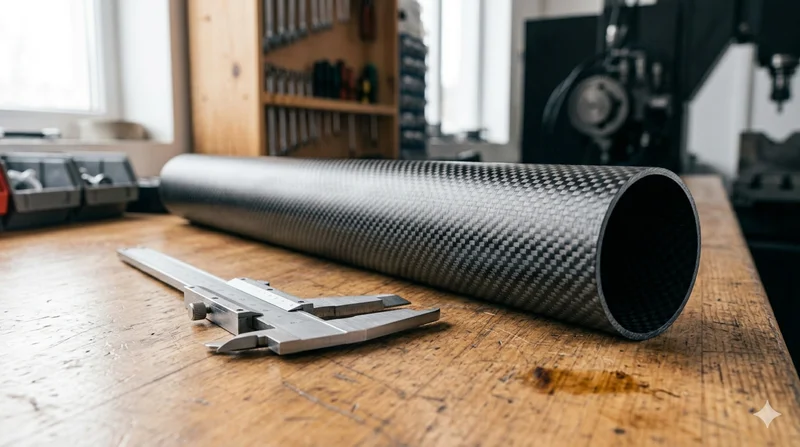
Round Carbon Fiber Tube — 3K Plain Weave T700
Standard round carbon fiber tube manufactured from Toray T700 grade fiber with 3K plain weave. Offers balanced strength and stiffness for general industrial applications including robotics, automation, sports equipment, and aerospace structures.