
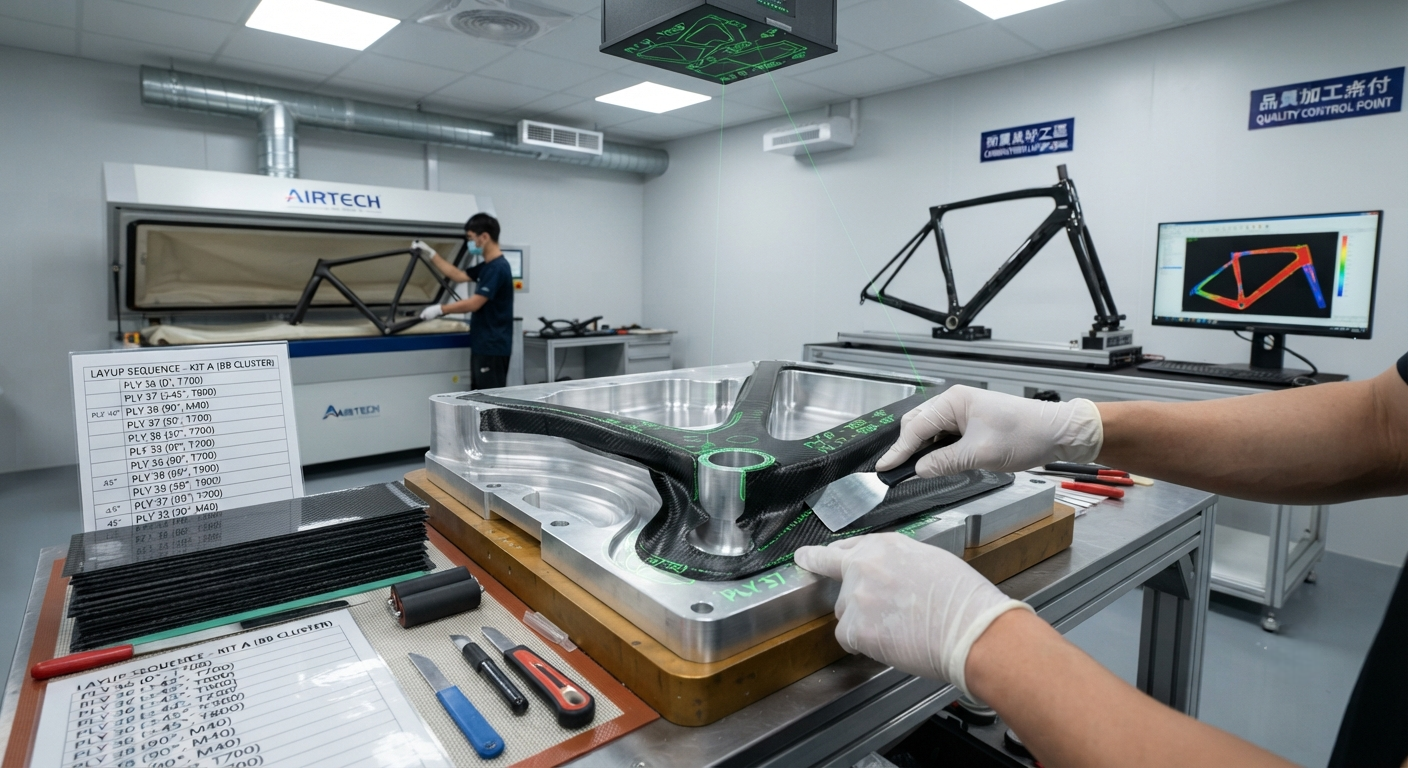
Technical deep-dive into carbon fiber bicycle frame layup schedule optimization — covering ply orientation principles, stacking sequence rules, fiber selection (SM/IM/HM/UHM), hybrid architectures, manufacturing constraints, and testing validation protocols for OEM engineers.
The Art and Science of Carbon Fiber Bike Frame Layup Design
Carbon fiber bicycle frame design has evolved from an artisanal craft into a data-driven engineering discipline over the past two decades, with layup schedule optimization emerging as the single most critical factor determining frame weight, stiffness distribution, ride quality, and durability. The layup schedule — the sequence of ply orientations, stacking order, and material selection across each tube and joint of the frame — dictates how the frame responds to pedaling loads, braking forces, road vibrations, and impact events. For bicycle OEM engineers, mastering layup optimization is the difference between a frameset that wins WorldTour races and one that fails catastrophically under fatigue loading.
A modern carbon fiber bicycle frame typically consists of 80–150 individual plies of carbon fiber prepreg, each 0.08–0.25 mm thick, arranged in a carefully engineered sequence across the bottom bracket, down tube, top tube, seat tube, head tube, chain stays, and seat stays. The total laminate thickness at any point on the frame ranges from 0.5 mm in lightly loaded areas (center of top tube) to 8–12 mm at high-stress junctions (bottom bracket shell, head tube). The selection of fiber orientations, ply shapes, and stacking order at each location determines the frame's local stiffness, strength, and damage tolerance characteristics.
Fundamental Ply Orientation Principles
The mechanical behavior of each frame tube is governed by the orientation of its constituent plies. Four primary orientation families are used in bicycle frame design, each serving a distinct structural function:
- 0° plies (axial): Aligned with the tube axis. These plies provide axial stiffness for pedaling efficiency — resisting bending of the down tube under crank loads and preventing flex in the chain stays under drivetrain torque. A typical high-performance frame uses 25–40% of total plies in the 0° orientation in the down tube and chain stays. Increasing 0° content above 45% yields diminishing returns in stiffness while adding unnecessary mass.
- ±45° plies (bias): Oriented at ±45° to the tube axis. These plies provide torsional rigidity — resisting twisting of the head tube during steering inputs and controlling the bottom bracket's lateral deflection under sprinting loads. ±45° plies are the most important orientation for ride quality tuning because they dominate the frame's damping characteristics. Typical content: 30–50% of total plies in the down tube and top tube, and 40–55% in the head tube junction.
- 90° plies (hoop): Oriented perpendicular to the tube axis. These plies provide hoop strength to resist internal molding pressure during manufacture and improve impact resistance from stone strikes and minor crashes. They also control transverse shrinkage during curing, reducing the risk of fiber wrinkling. Typical content: 10–20% of total plies in main triangle tubes.
- ±θ° intermediate plies: Orientations between 15° and 35° relative to the tube axis. These plies provide intermediate stiffness properties and are used primarily at tube junctions where load paths transition between orientations. They also serve to delay delamination at ply drop-offs by reducing interlaminar shear stress concentrations. Typical usage: 5–15% of total plies, concentrated at junctions and ply transition zones.
Stacking Sequence Optimization
The order in which plies are stacked — not just their individual orientations — has a profound effect on frame performance. The stacking sequence determines the laminate's bending stiffness (through thickness ratio), interlaminar shear stress distribution, and resistance to free-edge delamination. Core principles for bicycle frame stacking optimization include:
- Symmetric stacking: The ply sequence should be symmetric about the laminate mid-plane to prevent warpage during curing and to maintain consistent flexural behavior under positive and negative bending loads. A typical symmetric stack for a down tube might be [±45/0₂/90]s — with six plies on each side of the mid-plane, totaling 12 plies in the primary laminate.
- Surface ply placement: ±45° plies should be placed on the outer surfaces to maximize torsional stiffness per unit mass (since outer plies contribute most to polar moment of inertia). This also improves impact damage tolerance because ±45° surface plies resist splitting better than 0° plies when struck by road debris. Most production frames use a ±45° fabric (2×2 twill or plain weave) as the outermost cosmetic layer, which performs both structural and aesthetic functions.
- 0° ply grouping: Axial plies should be grouped in pairs or triplets near the laminate mid-plane to maximize axial stiffness without creating excessive bending-twisting coupling. Unidirectional 0° plies placed too close to the surface create asymmetric stiffness that induces twisting under axial load — a phenomenon known as bending-twisting coupling that degrades handling precision.
- Ply drop-off sequencing: Where plies terminate at tube junctions or along tapered tube sections (butted tube analogs), the drops should be staggered at 3–5 mm intervals with the drop-off direction alternating between inner and outer surfaces. Abrupt drop-offs — terminating more than two plies at the same location — create stress concentrations that initiate delamination under fatigue loading. Industry best practice limits ply drop-offs to a maximum of two plies per 5 mm of tube length.
| Frame Location | 0° Plies (%) | ±45° Plies (%) | 90° Plies (%) | ±θ° Plies (%) | Total Plies | Typical Thickness (mm) |
|---|---|---|---|---|---|---|
| Down tube (center) | 30–40 | 35–45 | 10–15 | 5–10 | 12–18 | 1.2–1.8 |
| Down tube (BB junction) | 35–45 | 30–40 | 8–12 | 8–12 | 40–60 | 4.0–6.0 |
| Top tube (center) | 15–25 | 45–55 | 15–20 | 5–10 | 8–12 | 0.8–1.2 |
| Seat tube (center) | 25–35 | 35–45 | 12–18 | 5–10 | 10–16 | 1.0–1.6 |
| Head tube junction | 25–35 | 40–55 | 8–12 | 8–15 | 50–80 | 5.0–8.0 |
| Chain stays | 35–45 | 25–35 | 10–15 | 5–10 | 14–20 | 1.4–2.0 |
| Seat stays | 10–20 | 40–50 | 15–20 | 10–15 | 8–12 | 0.8–1.2 |
| Bottom bracket shell | 30–40 | 35–45 | 8–12 | 10–15 | 60–100 | 6.0–10.0 |
Fiber Selection and Hybrid Architectures
The choice of carbon fiber reinforcement type — standard modulus (SM), intermediate modulus (IM), high modulus (HM), or ultra-high modulus (UHM) — has a dramatic impact on frame weight, stiffness, and cost. Modern high-performance frames increasingly employ hybrid fiber architectures that combine multiple modulus grades within a single layup to optimize the stiffness-to-weight ratio at each location.
- Standard modulus (230–250 GPa): T700-class fiber. Used in 50–70% of plies in mid-range frames ($1,500–$3,500 retail) and 30–50% of plies in high-end frames. Provides the best balance of strength, stiffness, and impact resistance for general-purpose frame construction. T700 is the primary material for entry-level and mid-tier framesets where cost per kilogram is a significant design constraint.
- Intermediate modulus (280–320 GPa): T800-class fiber. Used in 30–50% of plies in high-end frames ($4,000–$8,000 retail). Provides higher specific stiffness (stiffness per unit weight) than SM fiber, enabling 8–12% weight reduction for equivalent frame stiffness. IM fiber is preferentially placed in the bottom bracket area, down tube, and chain stays where stiffness requirements are highest.
- High modulus (340–400 GPa): M40-class fiber. Used selectively (5–15% of plies) in premium and ultralight frames ($8,000+ retail). HM fiber provides exceptional stiffness but at the cost of reduced strain-to-failure (0.5–0.8% versus 1.5–2.0% for SM fiber). HM plies are typically placed as core plies in the mid-plane of down tubes and top tubes, where they contribute maximum bending stiffness per unit mass while being protected from impact damage by outer IM and SM plies.
- Ultra-high modulus (400–460 GPa): M55J-class fiber. Used sparingly (2–5% of plies) in weight-weenie frames targeting sub-800-gram framesets. UHM fiber is extremely stiff but also extremely brittle — it cannot be used in single-fiber layups and must always be sandwiched between tougher IM or SM plies to prevent catastrophic failure under impact or overload conditions.
A state-of-the-art hybrid layup for a WorldTour-level frameset might be: outer cosmetic ±45° fabric (IM fiber, 2×2 twill, 200 g/m²) → ±45° IM bias plies → 0° IM axial plies (primary load-bearing) → HM 0° core plies (stiffness enhancement) → 90° SM hoop plies (crush resistance) → ±45° SM bias plies (damage tolerance). This architecture achieves a frame weight of 780–850 g (size M, painted) with a stiffness-to-weight ratio of 115–135 N·m/degree at the bottom bracket — exceeding the performance of 2015-era pure IM frames that weighed 900–1,000 g.
Manufacturing Constraints and Practical Considerations
Theoretical laminate optimization must contend with several manufacturing constraints that limit the layup designer's options. Understanding these constraints is critical for B2B buyers evaluating frame suppliers:
- Drapeability and ply conformity: High-modulus fibers (340+ GPa) are significantly stiffer in bending, making them difficult to conform to tight-radius features such as the bottom bracket shell, head tube junctions, and internal cable routing ports. SM and IM fibers with lower filament count (3K, 6K) are preferred for complex geometry areas. The minimum bend radius for UHM prepreg is approximately 5–8 mm at room temperature — features tighter than this require pre-heating the prepreg to 40–60°C to improve drapeability or substituting IM fiber.
- Bladder molding pressure: Internal bladder pressure during curing (typically 6–12 bar) generates hoop stresses that the laminate must resist without ply separation. Frames with excessive 0° content at the expense of ±45° and 90° plies are prone to bladder burst failures during manufacture — particularly at the down tube and seat tube where hydrostatic pressure is highest. The minimum recommended ±45° + 90° content for any tube cross-section is 35% of total plies.
- Joinery and tube-to-lug construction: Most production frames use monocoque construction (all tubes cured as a single structure in one bladder molding operation), but some manufacturers employ tube-to-lug or semi-monocoque processes where tubes are joined using internal socket lugs. These joints require additional ±45° wrapping plies at the lug interface — typically 3–5 additional bias plies extending 15–25 mm beyond the joint line — which adds 20–40 g per joint.
- Paint and surface finish considerations: Frames destined for high-gloss paint require a surface ply with minimal print-through of the underlying fiber weave. Using a finer weave (3K versus 12K tow) or a veil layer (30–50 g/m² non-woven mat) on the outer surface reduces fiber print-through. Matte-finish frames can use coarser weaves that are more economical but slightly heavier for equivalent stiffness.
Testing and Validation Protocols
Layup schedule optimization is validated through a comprehensive testing protocol that includes both physical testing and finite element analysis (FEA) correlation. The industry-standard testing framework — defined by ISO 4210 (safety requirements for bicycles) and supplemented by CEN standards and individual OEM protocols — includes:
- Static stiffness testing: Frame deflection measured under lateral pedal force (bottom bracket lateral stiffness), steering input (head tube torsional stiffness), and saddle load (seat tube deflection). Typical targets for a road racing frame: bottom bracket lateral stiffness > 80 N/mm, head tube torsional stiffness > 100 N·m/degree, and seat tube lateral stiffness > 50 N/mm.
- Fatigue testing: Multi-directional fatigue loading per ISO 4210-6 (pedaling force, horizontal force, vertical force) for 100,000–200,000 cycles at loads representing 1.5–2.5× maximum rider output. Layup optimization targets a fatigue safety factor of ≥ 1.5 at all frame locations, verified through strain gauge measurement at 30–50 locations per frame.
- Impact testing: Drop weight impact per ISO 4210-5 (falling mass impact on top tube) and localized impact resistance (stone strike simulation). Frames must survive a 10 kg mass dropped from 50 mm onto the top tube without structural failure — a test that particularly stresses the 90° hoop ply content and surface ±45° ply quality.
- Rider subjective evaluation: Blind A/B testing with professional cyclists provides the final validation. Key metrics include sprint stiffness (acceleration response under 1,200+ W output), cornering precision (steering accuracy under lateral load), vibration damping (road buzz attenuation at 20–100 Hz), and comfort over long-duration rides (4–6 hours). Layup modifications as small as 2–3 additional ±45° plies in the seat tube can meaningfully alter rider-perceived comfort.
Frequently Asked Questions
What is the optimal ply orientation percentage for a general-purpose road bike frame targeting balanced stiffness and comfort?
A balanced layup schedule for an endurance-oriented road frame (not a pure racing frame) typically follows a 25/45/20/10 split: 25% 0° axial plies for pedaling stiffness, 45% ±45° bias plies for torsional rigidity and vibration damping, 20% 90° hoop plies for impact resistance and manufacturing robustness, and 10% intermediate orientation plies at junction transitions. This distribution differs from a pure racing frame (35/40/15/10) by transferring 10% of the 0° ply budget to ±45° and 90° plies — a shift that reduces bottom bracket stiffness by approximately 8–12% but improves high-frequency vibration damping by 20–30% and impact damage tolerance by 15–25%. The resulting frame typically weighs 150–200 g more than an equivalent racing frame but delivers significantly better rider comfort on rough pavement and over long distances. For frame manufacturers serving the endurance and gran fondo market segments, this layup approach is the recommended starting point, with fine-tuning through FEA correlation and rider feedback across three to five prototype iterations.
How does ply drop-off design affect frame weight and durability?
Ply drop-off design is one of the most critical — and most frequently overlooked — aspects of layup schedule optimization in carbon fiber bicycle frames. Each ply termination point creates a discontinuity in the laminate that generates interlaminar shear stress concentrations. Poor drop-off design is the leading cause of frame fatigue failures (approximately 40% of all carbon frame warranty claims involve delamination originating at ply drop-off locations). Several key design rules govern optimal drop-off design: (1) Maximum drop-off rate: no more than two plies should terminate within any 5 mm length of tube — steeper drop-off rates create stress concentrations that initiate cracking at the resin-rich wedge formed at the termination point. (2) Staggered termination: adjacent plies should have their termination points offset by 3–5 mm, creating a gradual transition rather than an abrupt step. (3) Inner-surface termination preference: where possible, plies should terminate on the inner surface (inside the frame tube) rather than the outer surface, because the inner surface experiences lower tensile stresses under normal bending loads and because internal drop-offs are protected from impact damage by the outer continuous plies. (4) Cover ply requirement: every group of terminated plies should be covered by at least one continuous ply (typically a ±45° bias ply) that extends at least 10–15 mm beyond the last termination point to distribute the shear stress over a larger area. Frames that follow these design rules achieve fatigue lives 2–3× longer than those with poorly managed drop-offs, while adding only 10–20 g of additional material in the junction reinforcement plies.
What nondestructive testing methods are used to verify layup quality in production frames?
Production verification of carbon fiber bicycle frame layup quality employs a multi-tier NDT approach. (1) Visual inspection (100% of frames): every frame undergoes visual inspection for surface defects — porosity visible as pinholes in paint or clear coat, fiber print-through indicating uneven consolidation, and bond line gaps at tube junctions. Trained inspectors can identify manufacturing defects with approximately 85–90% sensitivity. (2) Ultrasonic A-scan (spot-check, 5–10% of frames): hand-held ultrasonic probes measure laminate thickness and detect delaminations and porosity at critical locations (bottom bracket, head tube, tube junctions). A-scan inspection takes 15–30 minutes per frame and is typically applied to the first 10–20 frames of a new production run and then to a 5% statistical sample thereafter. (3) Thermography (100% of premium frames): pulsed or lock-in thermography captures thermal diffusion patterns across the entire frame surface, revealing sub-surface delaminations, ply waviness, and inconsistent resin distribution. Modern thermography systems inspect a complete frameset in 60–90 seconds with defect detection resolution of 2–5 mm. (4) X-ray CT scanning (prototype and audit, < 1% of production): full-frame CT scanning provides three-dimensional visualization of the entire laminate architecture — ply orientation verification, thickness measurement at 25,000+ data points, void content analysis (target < 2% by volume), and fiber waviness quantification. CT scanning is primarily used for design validation (first-article inspection) and for investigating field failures, as the cost ($200–$500 per frame scan) and scan time (30–60 minutes) make it impractical for 100% production inspection. The industry trend is toward increasing use of automated thermography systems capable of 100% inspection at production line speeds, with several Asian frame manufacturers deploying inline thermal inspection stations that inspect every frame exiting the paint shop.
Part of topic
Related Articles
- Bio-Based Carbon Fiber Precursors: Lignin and Polyethylene for Low-Cost Production
- Large-Tow Carbon Fiber Cost Analysis: 48K vs 60K Price-Performance Comparison
- Carbon Fiber-Resin Interface Bonding: Surface Treatment and Coupling Agent Optimization
- Digital Twin for Carbon Fiber Manufacturing: Real-Time Process Monitoring and Defect Prevention
- Thermoplastic Carbon Fiber Welding for Automotive: Ultrasonic and Induction Welding Process Windows
- Large-Tow Carbon Fiber Wet Spinning: Process Optimization for 48K/60K Production Efficiency