
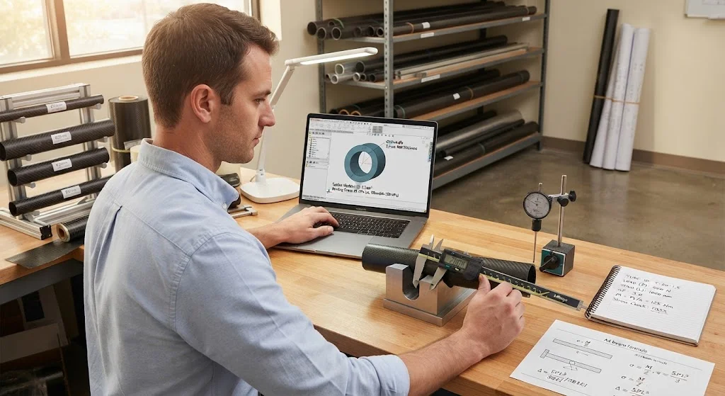
A carbon fiber tube strength calculator converts a known load into a tube diameter and wall thickness that will carry it safely, which is exactly what engineers need when a project moves from a rough sketch to a real part. Because carbon fiber tube is anisotropic, thin-walled and far stronger along
Introduction
A carbon fiber tube strength calculator converts a known load into a tube diameter and wall thickness that will carry it safely, which is exactly what engineers need when a project moves from a rough sketch to a real part. Because carbon fiber tube is anisotropic, thin-walled and far stronger along the fibers than across them, the calculation is not simply a metal sizing problem with a different density. This guide explains what a carbon fiber tube strength calculator actually solves, the formulas it is built on, the inputs it needs, a worked example, and the limits where a simple calculator must give way to full analysis.
Used well, such a calculator prevents the two common failures of amateur tube design: a tube so thin it buckles long before the fibers reach their strength, and a tube so heavy it wastes the mass advantage that made carbon fiber worth choosing in the first place.
What a Carbon Fiber Tube Strength Calculator Solves
A carbon fiber tube strength calculator answers three separate questions, and a good calculator keeps them apart because each has a different governing formula:
- Strength: Will the bending stress at the extreme fiber stay below the allowable stress, with a safety factor?
- Stiffness and deflection: Will the tube deflect less than the permitted limit under the working load?
- Stability and buckling: Will a thin wall or a long unsupported span buckle or cripple before it reaches its material strength?
In most lightweight carbon fiber tube designs, stiffness or buckling governs, not tensile strength. That is the first insight a calculator delivers: making the tube stronger rarely helps if the real problem is deflection.
The Core Formulas Behind a Carbon Fiber Tube Strength Calculator
The calculator relies on a small set of beam and column formulas applied to a hollow circular section. The table below lists the quantities used most often:
| Quantity | Formula | What it tells you |
|---|---|---|
| Second moment of area | I = pi (D^4 - d^4) / 64 | Bending stiffness of the section |
| Section modulus | Z = I / (D / 2) | Stress per unit bending moment |
| Bending stress | sigma = M / Z | Peak stress at the outer surface |
| Mid-span deflection, central point load | delta = F L^3 / (48 E I) | Sag under a point load |
| Euler buckling load | P = pi^2 E I / (K L)^2 | Load at which a column buckles |
| Torsional shear stress | tau = T (D / 2) / J | Shear stress from applied torque |
Here D is the outer diameter, d the inner diameter, L the span, E the axial modulus, M the bending moment, F the load, T the torque and K the effective-length factor set by the end conditions. A carbon fiber tube strength calculator simply evaluates these expressions and compares the results against allowable values.
Inputs You Need Before Using a Carbon Fiber Tube Strength Calculator
The output is only as good as the inputs, and the most common reason a calculator gives a misleading answer is that one of these was guessed:
- Outer and inner diameter: Usually taken from the catalogue; wall thickness is (D - d) / 2 and it drives both I and Z.
- Material properties: Axial modulus and strength for the specific layup, not a generic "carbon fiber" figure. A standard-modulus unidirectional tube runs near 120-135 GPa in bending.
- Span and end conditions: The unsupported length and whether the ends are pinned, fixed or free, which sets K for the buckling check.
- Load and load case: A point load differs from a distributed load, and impact or fatigue loads need their own factors.
- Safety factor: Typically 1.5 to 2.5 for static structures, higher where loads are uncertain or dynamic.
Carbon fiber tube weight then follows from the section area times length times density, so the same inputs also answer the "carbon fiber tube weight" question that always accompanies a sizing task.
Worked Example: Sizing a Tube for a Real Load
Consider a 1 metre simply supported carbon fiber tube carrying a 500 N central point load, with the limit set by a deflection target of 5 mm rather than by strength. In words, deflection equals the load times the span cubed, divided by 48 times modulus times the second moment of area. Taking E as 130 GPa, the required second moment of area works out to about 1.6 times ten to the fourth cubic millimetres, which a 20 mm outer diameter tube with a 2 mm wall satisfies comfortably. The bending stress in the same tube is then only a fraction of the 600 MPa allowable, confirming that stiffness, not strength, governs.
Run the same load on a thinner wall and the mode changes: at roughly a 0.8 mm wall the tube can begin to crush locally on the compression side before the fiber stress limit is reached, so a carbon fiber tube thick walled enough to resist local ovalisation may be needed even where the global bending calculation says otherwise.
Safety Factors and Where Simple Calculators Fall Short
A carbon fiber tube strength calculator treats the tube as a homogeneous elastic beam, which is reasonable for straight tubes under simple bending, but it misses several real effects. Local buckling and ovalisation of thin walls, the low shear and transverse strength of a unidirectional layup, stress concentrations at joints and inserts, and the drop from static to fatigue strength all sit outside a basic beam model. For a "carbon fiber tube vs aluminum" comparison, the calculator should also be run on the aluminum section, because carbon fiber wins on stiffness per kilogram while aluminum is more tolerant of local damage.
The right use of a carbon fiber tube strength calculator is therefore first-pass sizing: it narrows the field to two or three candidate tubes, which then deserve coupon testing or a bonded-joint analysis before a production commitment.
Frequently Asked Questions
How do I calculate the strength of a carbon fiber tube?
Start with the second moment of area of the annulus, then the section modulus, then the bending stress from the applied moment. Compare that stress with the allowable and apply a safety factor. If the tube is long or the wall is thin, also check Euler buckling and local crushing, because these often govern before material strength does. A carbon fiber tube strength calculator automates this sequence, but the governing check still has to be interpreted by the engineer.
Is a thick-walled carbon fiber tube stronger than a thin-walled one?
A thicker wall raises both stiffness and local buckling resistance, so it is stronger up to a point, but it also adds weight and can change the failure mode. Beyond a certain wall-to-diameter ratio the tube becomes mass-inefficient, because the extra material sits near the neutral axis where it barely resists bending. For a given outer diameter, increasing wall thickness adds strength fastest in the range where local buckling is the limiting mode.
When is a carbon fiber tube better than an aluminum tube?
Carbon fiber tube wins whenever stiffness or strength per kilogram matters, because its specific modulus and specific strength are several times those of aluminum. An aluminum tube is preferable where local impact tolerance, cheap machining or a bolted connection is needed. The honest test is to run both sections through the same calculator and compare deflection, mass and failure mode, rather than to assume that the lighter material is automatically correct.
Conclusion
A carbon fiber tube strength calculator is a fast, useful first-pass tool that turns a design load into a candidate tube section, provided the engineer understands that stiffness or buckling usually governs a lightweight carbon tube, not tensile strength. The formulas for second moment of area, bending stress, deflection and Euler buckling are simple, but their inputs and assumptions decide whether the result is trustworthy. Used as a filter rather than a final answer, the calculator saves time and material on every tube-sizing task.
If you need carbon fiber tubes supplied to a defined diameter, wall thickness and layup for your sizing calculations, browse our carbon fiber tube range, or contact our team for section datasheets and sizing support.
Part of topic
Related Articles
- Carbon Fiber Sheet Cutting: Methods, Tools and Edge Quality
- Carbon Fiber Sheet Thickness: Standard Sizes and Selection Criteria
- Carbon Fiber Sheet Molding Compound: Process, Properties and Applications
- Carbon Fiber Sheet Density: Areal Weight, Fiber Volume and Laminate Density
- Carbon Fiber Tube Cutting: Clean Square-End Techniques for Production
- Carbon Fiber Plate Cutting: CNC, Waterjet and Hand Routing Compared
Interested in Our Products?
Contact our team for competitive pricing and technical specifications.
Get a QuoteRelated Products

Carbon Fiber Plate — 3K Twill T700 3.0mm
Medium-thickness 3.0mm carbon fiber plate offering significantly higher load capacity while maintaining attractive 3K twill finish. Suitable for structural brackets, reinforcement plates, and load-bearing panels.

Carbon Fiber Plate — 3K Twill T700 1.5mm
Thin 1.5mm carbon fiber plate with 3K twill weave surface. Lightweight and stiff, commonly used for covers, panels, drone bodies, and applications requiring a premium aesthetic appearance.

Square Carbon Fiber Tube — 3K Twill T700
Square cross-section carbon fiber tube manufactured with 3K twill weave for torsional strength. Preferred for structural frames, trusses, and support columns where rectangular geometry offers design flexibility.

Carbon Fiber Pickleball Paddle
High-performance pickleball paddle with Toray T700 carbon fiber face and polypropylene honeycomb core. Delivers excellent power-to-weight ratio, spin generation, and vibration dampening for competitive play.

Carbon Fiber Trekking Pole
Lightweight carbon fiber trekking pole manufactured from high-grade carbon fiber tube. Weighs only 160g per pole while providing superior shock absorption and durability for hiking, trail running, and backpacking.