
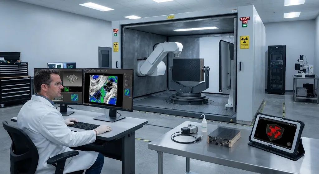
Thick composite laminates carry the highest loads in modern structures, yet they are the most difficult to inspect. A wind turbine blade root, an aircraft wing attachment lug, or a helicopter rotor hub bolt region can exceed 25 millimeters of laminate thickness, and in these sections th
Introduction
Thick composite laminates carry the highest loads in modern structures, yet they are the most difficult to inspect. A wind turbine blade root, an aircraft wing attachment lug, or a helicopter rotor hub bolt region can exceed 25 millimeters of laminate thickness, and in these sections the two great enemies of composite quality, voids and fiber waviness, have the largest effect on strength. The industry default inspection method, pulse-echo ultrasound, attenuates rapidly through thick carbon fiber laminate, leaving inspectors with either a weak signal or a requirement to inspect from both sides with multiple probes. X-ray computed tomography (CT) removes this limitation by reconstructing the full 3D volume of the part, making it the most powerful method available for thick-section quality verification.
This article explains how X-ray CT is applied to thick carbon fiber laminates, what void detection limits it actually delivers, and how the 3D data it produces goes beyond porosity to reveal fiber waviness, ply wrinkles, and local fiber volume fraction variations. It closes with practical guidance on where CT fits in a production quality program, balancing scan cost and speed against the value of catching defects that no other method sees.
Why Thick Laminates Are Hard to Inspect
The physics of ultrasonic inspection explains the difficulty. Ultrasound energy is absorbed and scattered by carbon fibers, and through-thickness attenuation in a unidirectional carbon laminate rises steeply with both frequency and thickness. Inspectors face a trade-off: higher frequency gives better resolution of small voids but attenuates faster, while lower frequency penetrates further but cannot resolve defects below roughly 1-2 millimeters in size. For laminates above 15-20 millimeters, practical frequencies drop to 1-2 MHz, and detection of fine porosity becomes unreliable.
Thick sections also complicate the interpretation of echoes. The back-wall echo, used to detect delaminations, weakens and blurs; multiple probe passes from both sides are needed; and the curved surfaces typical of blade roots and lugs make coupling inconsistent. None of these limitations apply to CT, which reconstructs a voxelized volume independent of part surface geometry. A single scan of a 25 millimeter laminate resolves voids down to roughly 100-200 micrometers, an order of magnitude better than through-transmission ultrasound at practical production speeds.
How X-Ray CT Works for Composites
In industrial CT, the part rotates on a turntable between an X-ray source and a flat-panel detector while hundreds or thousands of projection images are recorded. A reconstruction algorithm, typically filtered back-projection or iterative reconstruction, converts the projections into a 3D volume of voxels, each voxel carrying a gray value proportional to local X-ray attenuation. Carbon fiber, epoxy matrix, porosity, and any metallic inserts attenuate differently, so the reconstructed volume directly separates resin-rich areas, fiber bundles, and voids.
Two parameters dominate scan quality. First, resolution, which is set by the focal spot size of the source, the detector pixel pitch, and the geometric magnification, and which determines the smallest void that can be resolved. Second, scan time, which scales with the number of projections and the power needed to penetrate the thickness; a 300 millimeter scan volume at 150 micrometer resolution typically takes 10-30 minutes including reconstruction. For thick carbon laminates, the practical challenge is the source energy: thicker sections need higher kilovoltage, and the contrast between carbon and void, which is inherently low because both have low atomic number, requires careful beam hardening correction.
| Inspection method | Typical void resolution | Depth limit | 3D data | Production speed |
|---|---|---|---|---|
| X-ray CT | 100-300 µm | None practical (limited by part size) | Full volume | Minutes to hours per part |
| Through-transmission ultrasound | 1-2 mm | Attenuation-limited, roughly 50-100 mm | 2D projection | Fast, in-line |
| Pulse-echo ultrasound | 1-3 mm | 15-25 mm before signal loss | 2D slices | Fast, in-line |
| Shearography | 2-5 mm (planar defects) | Surface-sensitive | 2D strain map | Fast, full-field |
| Destructive microscopy | Below 10 µm | Sample only | Local sections | Destructive, offline |
Void Detection and Porosity Measurement
Voids are the primary concern in thick composite sections because they act as stress concentrators that initiate delamination under cyclic loading, and their effect scales with both size and volume fraction. CT quantifies porosity in ways that destructive testing cannot match. The segmented void volume gives total porosity percentage, void size distribution, and the spatial location of every individual void, which matters because a cluster of voids in a bolt-load path is far more damaging than the same volume fraction scattered harmlessly in a low-stress zone.
Calibration matters: CT porosity values are only as good as the segmentation threshold applied to the gray values, and validation against acid digestion or microscopy on a reference coupon is standard practice. With proper calibration, CT agrees with destructive measurements within roughly plus or minus 0.3% porosity on production laminates. The scan also catches void morphology, distinguishing spherical voids from process-related elongated voids aligned with fiber direction, a distinction that guides the process engineer to the root cause.
Beyond Voids: The 3D Quality Data Advantage
The decisive advantage of CT over traditional NDT is that the reconstructed volume is permanent 3D data, not a 2D projection, and it can be mined for defects that ultrasonic methods do not see at all:
- Fiber waviness and ply wrinkles: out-of-plane waviness in a thick laminate can reduce compressive strength by 30-50% while remaining invisible to ultrasound. CT measures the local fiber orientation field across the full volume, converting a suspected wrinkle into a quantified angle map.
- Fiber volume fraction mapping: gray values correlate with local fiber content, giving a 3D map of resin-rich and fiber-rich zones. This reveals resin pooling at ply drops or corners that coupon testing misses.
- Delamination and crack networks: CT resolves the 3D extent of disbonds and cracks, which matters for evaluating impact damage where the damage path is rarely planar.
- Metallic insert and fastener verification: the same scan verifies insert position, tilt, and surrounding resin fill in bolted regions of thick laminates.
- Digital archive and finite element correlation: the CT volume can be meshed directly into structural models, allowing strength analysis on the as-built geometry with real defect fields.
Practical Deployment in a Quality Program
CT will not replace ultrasonic inspection in high-volume production; it is too slow and too expensive per part. The pattern that works in practice is a layered strategy. Fast ultrasonic scanning covers every part in production and flags anomalies; CT is deployed where the risk concentration justifies the cost: first-article qualification of a new part, re-qualification after a process change, audit sampling of thick load-bearing sections, and full 3D documentation of a critical failure or repair. Scan cost scales with volume, with a 100-300 millimeter laminate section typically costing a few hours of equipment time plus reconstruction, which is trivial compared with the cost of a blade root or wing lug failure.
CT also changes acceptance criteria design. Because it sees void clusters and waviness in 3D, acceptance can move from a global porosity percentage to a position-dependent limit, for example a stricter void limit in the bolt-bearing zone than in the web of a section. This is the direction the industry is moving: porosity limits defined in space, not just in aggregate.
Frequently Asked Questions
How does X-ray CT compare with ultrasonic testing for void detection in thick laminates?
CT resolves voids down to roughly 100-300 micrometers anywhere in the part volume, independent of part thickness, while ultrasound in thick carbon laminate is limited to voids above about 1-2 millimeters by attenuation. CT also delivers the full 3D spatial distribution of voids, not just a projected image, and detects fiber waviness that ultrasound cannot see. The trade-off is cost and speed: CT takes minutes to hours per part and higher equipment investment, so it is deployed for qualification, audit sampling, and critical sections rather than 100% in-line inspection.
What is the smallest void size that industrial CT can detect in carbon fiber laminate?
With a micro-focus source and a laboratory CT system, voids of 10-50 micrometers can be resolved in small coupons. On production-sized thick sections, where the source energy and geometric magnification are constrained by part size, the practical detection limit is roughly 100-300 micrometers. The more relevant metric for design is not the smallest single void but the porosity volume fraction and its spatial distribution, which CT measures reliably with calibration against destructive testing.
Is CT inspection feasible for full wind turbine blade roots or large aircraft parts?
For parts larger than the CT system's scanning envelope, the standard approach is regional scanning of the highest-risk zones, typically the thickest laminate and the bolt regions, plus sub-scale coupons scanned at higher resolution for process validation. Some facilities use linear-accelerator CT systems with larger envelopes for complete blade root sections, though cost and cycle time restrict this to qualification programs. The 3D data from regional scans is usually sufficient to validate the process and the critical zones, while full-part coverage remains impractical at production volumes.
Conclusion
Thick composite laminates concentrate load, risk, and inspection difficulty in the same volume, and X-ray CT is the only practical method that resolves voids and fiber architecture in 3D across those thicknesses. With detection limits an order of magnitude better than ultrasound on thick sections, and the ability to quantify waviness, fiber volume fraction, and void position, CT turns quality assurance from a pass-fail gate into a source of engineering data that feeds design and process improvement. For manufacturers of blade roots, aircraft fittings, and structural lugs, CT is not an alternative to ultrasonic production screening, but the qualification and audit layer that gives the screening meaning.
For engineers setting up inspection strategies for thick-section parts, the starting point is a risk-based decision on which zones justify CT, followed by calibration of porosity thresholds against destructive testing. Explore our carbon fiber materials and structural solutions, or contact our engineering team to discuss material qualification and inspection requirements for your program.
Part of topic
Related Articles
- Pultruded Carbon Fibre Rods: Cross-Sectional Properties and Standard Sizes
- Carbon Fiber Tube Fittings and Connectors: Joining Solutions for Structural Assemblies
- Carbon Fiber Plate Insert: Threaded Insert Design for Composite Structures
- Filament Wound Epoxy Tubing: Selection Guide for Industrial and Aerospace Applications
- Filament Wound Epoxy Tubes Advantages: Over Metal and Pultruded Alternatives
- Carbon Fiber Tube Strength: Analysis Methods and Design Allowables
Interested in Custom Carbon Fiber Products?
Contact our team for competitive pricing and technical specifications.
Get a QuoteRelated Products

Carbon Fiber Fishing Rod Blank
High-quality carbon fiber fishing rod blank manufactured from multiple grades of Toray carbon fiber cloth. Available in a wide range of lengths, powers, and actions for freshwater and saltwater applications. Suitable for OEM rod building.

Custom Carbon Fiber Medical Device Components
Medical-grade carbon fiber components manufactured for imaging equipment, surgical instruments, and patient support systems. Carbon fiber's radiolucency (X-ray transparency) and high strength-to-weight ratio make it ideal for CT scanner beds, wheelchair frames, surgical robot arms, and MRI-compatible accessories. Biocompatible resin systems available.
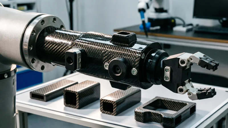
Carbon Fiber Robot End Effector Link — Custom Shape & Sensor Integration
Custom-shaped carbon fiber end effector links for robotic arms. Designed for automation integrators and research labs requiring lightweight, rigid connections between the robot wrist and gripper/tool. Can incorporate sensor mounting bosses, cable routing channels, and quick-change interfaces.

Custom Carbon Fiber Musical Instrument Parts
Carbon fiber components for musical instrument manufacturing offering superior dimensional stability, low weight, and consistent acoustic properties. We produce carbon fiber bows, guitar necks, violin chin rests, drum shells, and wind instrument bodies. Carbon fiber instruments are immune to humidity changes and temperature fluctuations that affect wooden instruments.
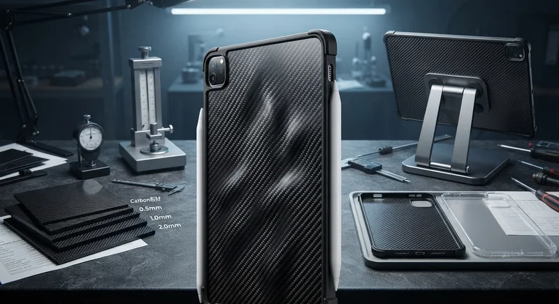
Carbon Fiber Tablet Case — Ultra-Light Protective Shell
Lightweight carbon fiber protective case for tablets and iPads. Molded from T700 3K prepreg with reinforced corner protection. Adds minimal weight while providing superior rigidity and drop protection compared to polycarbonate or silicone cases. Ideal for field workers, enterprise deployments, and professionals requiring durable tablet protection.