
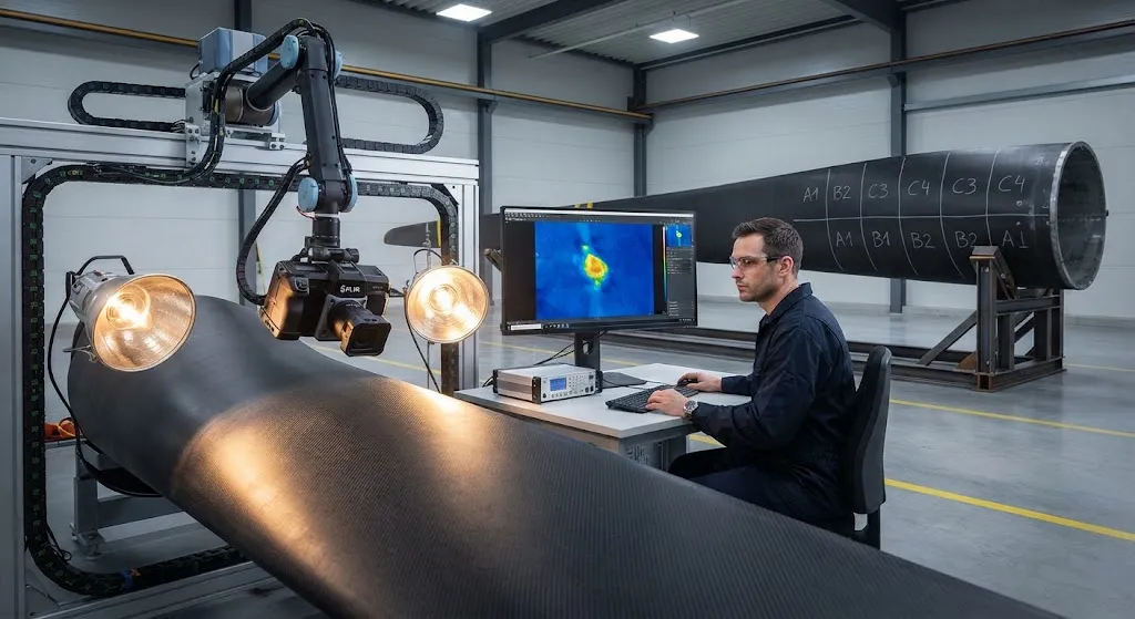
Infrared thermography occupies a unique position in the composite inspection toolkit: it is the only mainstream nondestructive testing method that inspects a large surface area as fast as a camera can image it. A thermal camera scanning an eight-meter wind blade section can cover the eq
Introduction
Infrared thermography occupies a unique position in the composite inspection toolkit: it is the only mainstream nondestructive testing method that inspects a large surface area as fast as a camera can image it. A thermal camera scanning an eight-meter wind blade section can cover the equivalent of hundreds of ultrasonic contact points in a single frame, revealing subsurface disbonds, delaminations and water ingress without contact, couplant or surface preparation. For carbon fiber structures that are simultaneously large, curved and fatigue-loaded — wind turbine blades, aircraft control surfaces, radomes — this throughput advantage is decisive.
Thermography is divided into two methodological families. Passive thermography observes thermal patterns that exist naturally during operation or testing. Active thermography applies a controlled thermal stimulus to the surface and records how the heat diffuses through the material, exposing internal defects as localized temperature anomalies. Both families have specific niches in blade and aircraft inspection, and both are increasingly automated with robotic scanners and AI-assisted image analysis.
The Physics of Thermal Inspection
Infrared thermography measures the surface temperature distribution with a cooled or uncooled thermal camera, typically operating in the 3-5 or 7-14 µm wavebands. When a defect lies below the surface, it alters the local thermal conductivity of the composite: an air-filled delamination conducts heat far more poorly than solid laminate, so the region above it cools or heats at a different rate than the surrounding sound material. The camera records these transient differences as bright or dark areas in a thermal image sequence.
Three material properties govern performance: thermal diffusivity, emissivity and thickness. Carbon fiber composites have anisotropic diffusivity — roughly 3-7 times higher along the fibers than through the thickness — which bounds the practical detection depth. The thermal diffusion length, which scales with the square root of the inspection time, sets the maximum depth at which a defect can be resolved: for flash thermography on carbon fiber, reliable detection typically extends to 1-3 millimeters below the surface, depending on the pulse energy and defect size. Emissivity variations from glossy resin surfaces are managed with high-emissivity coatings or mathematical corrections during data processing.
Active Thermography Methods
Active thermography stimulates the surface before imaging, and the method of stimulation defines the sub-technique:
- Pulsed (flash) thermography: Xenon flash lamps deliver a millisecond-scale heat pulse, and the camera records the cooling transient over the following seconds. Fast, single-sided, and ideal for thin skin panels and bonded repairs; detection depth is limited by the short observation window.
- Lock-in (modulated) thermography: The excitation is modulated sinusoidally, and the camera extracts the amplitude and phase of the thermal response at the modulation frequency. Phase images suppress surface emissivity artifacts, and lower frequencies probe deeper — typically 1-10 millimeters — at the cost of longer acquisition times.
- Step heating thermography: A constant heat flux is applied for a sustained period while the camera monitors the temperature rise. Suited to thick laminates and quantitative measurement of thermal properties, with acquisition times of tens of seconds per scan region.
Table-based comparisons below summarize the operating trade-offs for blade and aircraft inspection scenarios.
Method Comparison at a Glance
| Method | Excitation | Depth Range | Scan Speed | Best For |
|---|---|---|---|---|
| Pulsed (flash) thermography | Xenon flash, 1-5 ms | 1-3 mm | 0.5-2 m²/min | Skin panels, bonded patches, core inspection |
| Lock-in thermography | Modulated halogen lamps, 0.01-1 Hz | 1-10 mm | 0.2-1 m²/min | Delamination depth binning, thick laminates |
| Step heating thermography | Constant heat flux, 10-60 s | 2-8 mm | 0.1-0.5 m²/min | Thick laminate quantification, material property measurement |
| Passive thermography | None (operational or load heating) | Surface and near-surface | Real time | In-service monitoring, fatigue crack hot spots |
No single method dominates: flash thermography wins where speed per square meter matters on thin structures, lock-in wins where depth information matters, and passive inspection wins where parts are already loaded or operating.
Comparison With Ultrasonic and Shearography
Thermography does not replace established methods; it complements them where they are slow. The decision matrix for blade and aircraft inspection is:
- Ultrasonic testing: Gold standard for depth-resolved detection in thick or mission-critical structures. Contact and phased-array variants deliver millimeter accuracy, but point-by-point scanning of large areas is slow and requires couplant; thermography is 10-100 times faster per square meter.
- Shearography: Full-field optical method that detects surface strain anomalies under vacuum or thermal load. Excellent for honeycomb core disbonds but requires an enclosed, vibration-isolated environment and laser speckle technology, making it less portable than an IR camera rig.
- X-ray computed tomography: Unmatched for internal 3D detail and void quantification on small samples, but impractical for blade-scale parts due to cost, radiation safety and size limits.
In practice, thermography serves as the screening layer: it flags suspect regions across the entire blade or panel quickly, and ultrasonic or shearographic methods verify the flagged areas in detail. This layered workflow cuts total inspection time by 50-80 percent in production and field settings.
Industrial Applications: Blades and Aircraft
Thermography has moved from laboratory demonstrations to standardized industrial workflows in three application areas:
- Wind blade manufacturing QC: Adhesive bonds between spar caps and shear webs, and the trailing edge bond line, are inspected inline after cure. Robotic or gantry-mounted IR scanners acquire full blade coverage in under two hours, compared with several days of manual ultrasonic contact scanning. Disbonds smaller than 5-10 mm are reliably resolved in the 2-8 mm laminate thickness range of typical blade skins.
- In-service blade inspection: Passive thermography detects water ingress and impact damage during operation or blade slow-rotation checks, because water-filled and delaminated regions retain or transport heat differently. Combined with drone-mounted cameras, thermography now supports remote blade surveys at turbine sites before a technician climbs the tower.
- Aircraft part inspection: Composites on radomes, flight control surfaces, engine cowls and secondary structures are screened with flash thermography during scheduled maintenance. Bonded repair patches are re-inspected after cure, and passive methods monitor hot spots in engine bay insulation and acoustic panels during ground runs and taxi tests.
Qualification and Practical Considerations
Thermography earns aerospace and wind-industry acceptance when the inspection procedure is qualified against known reference defects. Practical implementation requires attention to four factors. First, calibration: the system must be validated with embedded-flaw reference panels — Teflon inserts or machined flat-bottom holes at known depths — matching the part's laminate thickness. Second, surface condition: glossy carbon surfaces can produce emissivity-related false signals, addressed by matte coating, angle selection or phase-based lock-in processing. Third, environmental control: convective air currents, sunlight and reflective backgrounds corrupt thermal data, which is why field inspections favor dawn, dusk or overcast conditions and shielded enclosures in production. Fourth, data processing: modern systems integrate automated motion tracking, frame alignment and AI-based defect classification, with defect size thresholds tuned to the qualifying reference panels before routine deployment.
Frequently Asked Questions
How deep can infrared thermography detect defects in carbon fiber composites?
Detection depth depends on the method and observation time. Flash thermography typically resolves defects 1-3 millimeters below the surface in carbon fiber laminates, because the thermal diffusion length is limited by the short observation window. Lock-in thermography with low modulation frequencies reaches 1-10 millimeters by letting heat diffuse longer, while step heating covers roughly 2-8 millimeters. Defects deeper than these ranges are usually assigned to ultrasonic or radiographic methods, which are not limited by thermal diffusion.
Is thermography suitable for inspecting an entire wind turbine blade in the field?
Yes, with practical constraints. Manufacturing QC can scan a complete blade in under two hours with robotic or gantry-mounted IR systems. In the field, drone-mounted or telescopic-boom cameras perform passive surveys, detecting water ingress, impact damage and gross disbonds during slow rotation or natural thermal cycles; active stimulation is less practical outdoors because of ambient heating and airflow. Field thermography is therefore most effective as a rapid screening layer, with confirmatory ultrasonic inspection of flagged regions.
What defects can thermal inspection reliably identify in composite parts?
Thermography reliably identifies disbonds, skin-to-core delaminations, impact damage, water ingress, and porosity clusters in near-surface regions, as well as thermal anomalies indicating material degradation in service. Its blind spots are defects far below the thermal diffusion depth, fine cracks smaller than the pixel-limited resolution, and deep voids at the far side of thick laminates. As with all NDT methods, reliable detection depends on qualifying the procedure against representative reference defects before production deployment.
Conclusion
Infrared thermography has become the standard screening layer for large-area carbon fiber inspection, pairing minute-level full-surface coverage with reliable detection of disbonds, delaminations and water ingress in the near-surface zone. Active methods deliver controlled, quantitative inspection in manufacturing; passive methods extend coverage to operating blades and aircraft in service. Layered with ultrasonic or shearographic confirmation, thermography cuts composite inspection time by 50-80 percent across the blade and aerospace sectors.
For manufacturers integrating NDT into composite production, thermography pairs naturally with advanced reinforcement materials. Explore our range of carbon fiber fabrics and laminates, or contact our engineering team to discuss inspection-compatible material systems for your parts.
Part of topic
Related Articles
- Pultruded Carbon Fibre Rods: Cross-Sectional Properties and Standard Sizes
- Carbon Fiber Tube Fittings and Connectors: Joining Solutions for Structural Assemblies
- Carbon Fiber Plate Insert: Threaded Insert Design for Composite Structures
- Filament Wound Epoxy Tubing: Selection Guide for Industrial and Aerospace Applications
- Filament Wound Epoxy Tubes Advantages: Over Metal and Pultruded Alternatives
- Carbon Fiber Tube Strength: Analysis Methods and Design Allowables
Interested in Our Products?
Contact our team for competitive pricing and technical specifications.
Get a QuoteRelated Products

Carbon Fiber Fishing Rod Blank
High-quality carbon fiber fishing rod blank manufactured from multiple grades of Toray carbon fiber cloth. Available in a wide range of lengths, powers, and actions for freshwater and saltwater applications. Suitable for OEM rod building.

Carbon Fiber Plate — 3K Twill T700 1.5mm
Thin 1.5mm carbon fiber plate with 3K twill weave surface. Lightweight and stiff, commonly used for covers, panels, drone bodies, and applications requiring a premium aesthetic appearance.

Custom Carbon Fiber Medical Device Components
Medical-grade carbon fiber components manufactured for imaging equipment, surgical instruments, and patient support systems. Carbon fiber's radiolucency (X-ray transparency) and high strength-to-weight ratio make it ideal for CT scanner beds, wheelchair frames, surgical robot arms, and MRI-compatible accessories. Biocompatible resin systems available.

Square Carbon Fiber Tube — 3K Twill T700
Square cross-section carbon fiber tube manufactured with 3K twill weave for torsional strength. Preferred for structural frames, trusses, and support columns where rectangular geometry offers design flexibility.
Carbon Fiber Drone Arm
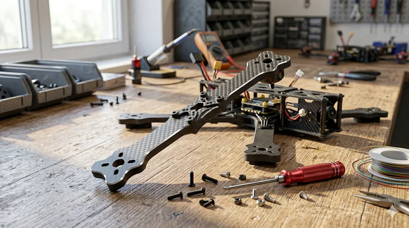
Precision-molded carbon fiber drone arm combining unidirectional fiber for stiffness and woven layers for torsional strength. Designed for FPV, photography, and industrial drone platforms. Each arm is CNC-machined to exact specifications.